(this was posted to Classic Computer mailing list, please disregard if you’re on the list. I think this is an important topic)
The last two nights I’ve been busy archiving some of my Amiga floppy collection. Most disks were written over 20 years ago.
On a sample size of about 150 floppies, most of them were perfectly readable by my homegrown usb external amiga floppy drive controller.
I paid very close attention to the failures or ones where my controller struggled.
Without sounding too obvious here, the time between the pulses (which more or less define the data) were grossly out of spec. The DD pulses should nominally be 4us, 6us, and 8us apart before pre-write compensation. Most good disks are slightly faster, and normal times for these ranges are:
4us: 3.2-4.2us. Many around 3.75us
6us: 5.5-6.2us.
8us: 7.5-8.2us
(notice margins around 1-1.3us)
My original microcontroller implementation was 3.2-4.2, 5.2-6.2, and 7.2-8.2.
When my current FPGA controller would have a problem, I’d notice that there were problems right on a boundary. So maybe pulses were coming in at 3.1us apart instead of 3.2. Or maybe 4.3 instead of 4.2. So I kept bumping the intervals apart, making a larger range of pulse times acceptable — the XOR sector checksums were passing, so I was likely making the right choices. The bits were ending up in the right buckets.
But as I went through some of these disks, I ended up with the difference between ranges(and basically my noise margin) being reduced smaller and smaller. Some to the point where an incoming pulse time might fall darn smack in the middle of the noise margin. Which bucket does THAT one go into?
My approach has been very successful(easily 95%+), but it makes me wonder about Phil’s DiscFerret dynamic adaptive approach where a sample of the incoming data defines the ranges.
Some disk drives and controllers might be faster or slower than others, and if you create custom ranges for each disk (each track?), perhaps you’ll have better luck.


Hi
Try to implement a data separator instead of doing this when pulses are sampled.
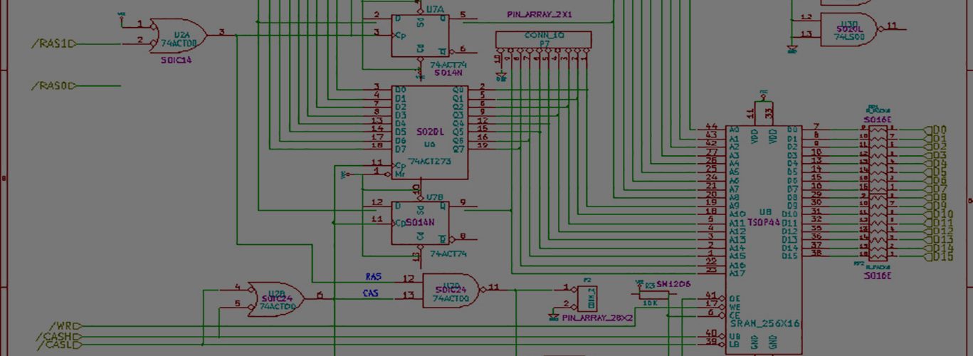
At the link is the schematic of data separator from my WD 179x based floppy controller, I built for 8 bit computer in late 80s. It works as the digital phase lock loop. It synchronizes the data flow to 4/8 MHz clock from the controller first. Then, it recovers the clock signal from the MFM modulation. At the output, there are two signals: Data and clock. DATA_O contains both data and clock pulses and CLOCK_O says when to shift them to the shift register.
https://www.tomas-franke.cz/speccy/sep.png
How does look the low level format of Amiga floppy track?
Thanks very much for your comment!
I am in the process of trying Jim Thompson’s Floppy Data Extractor which I just recently did a schematic capture of inside Xilinx’s ISE. I’ve got to look at your design, but they seem similar.
https://www.analog-innovations.com/SED/FloppyDataExtractor.pdf
He calls this the PJL, phase-jerked loop.
From what I can tell, I just have to count the number of RCLK pulses between edges.
I’m not sure exactly what you are asking about the Amiga floppy track, but generally
bitcells are 2us, so raw MFM data rate is 500kbps.
Edges from drive appear roughly 4us, 6us, or 8us apart.
I’m doing double density disks only right now.
There is no gap between sectors, all sectors are written in a row at the same time per track. Tracks are made up of 11 sectors at 1088 RAW MFM bytes per sector. 11,968 raw MFM bytes per track. This is 5984 real bytes per track, or 544 per sector. 32 bytes of sector header, and 512 bytes of data.
Each sector has a sync header of 0xAAAA AAAA 4489 4489.
This should give you a pretty good idea of what it looks like. 🙂
Yes the data separator works the same way as mine.
I need something that can read Amiga floppies to image files for emulator
My project will definitely work but you’ll need the eval board, add on prototyping board, a floppy data connector, a few resistors, and of course a pc floppy drive and cable.