Despite having a couple different official sources, both AFR.c and floppy.c from the fellow amiga emulator says that the even bits come before the odd bits.
This is true in the sector header decoding as well as in the data decoding.
I haven’t extensively manually tested this, but it appears to be working OK for their routines.
It is pretty odd, no pun intended.
While I don’t think it matters much, I find the discrepancy to be unnerving. While I can’t provide online links to most of the sources, the sources were CLEAR in the fact that the ODD bits were first to be written and then followed by the EVEN bits.
Wierdo.
Its 1:47am and I need sleep.


I use ‘The .ADF (Amiga Disk Format) FAQ’ as the ultimate reference 🙂
https://lclevy.club.fr/adflib/adf_info.html#p23
It says first go even bits, then odd ones.
Just occured to me (well, I’ve got enough sleep for last couple of days) that there probably is little to no difference at all as to wether odd bits follow even or vice versa.
Since resulting byte is obtained by combining (using logical OR) odd and even bits together, it doesn’t matter in what order are bits processed. In other words, if we have 0xFF byte its even bits are 0xAA and odd bits are 0x55. Either 0xAA ORed with 0x55, or 0x55 ORed with 0xAA, you still get 0xFF in the end.
Yeah that .ADF faq is awesome. I use it as well.
What about the left shift? You can’t left shift the even’s when it was supposed to be the odd’s right, and still have the same effect?
A friend of mine has access to some of the original assembly source code used in the actual amiga. I examined the source myself, and the “implementation notes” at the beginning of the source are pretty clear and even give a sample code-line for decoding:
((odd bits word & 0x5555) << 1) | (even bits word & 0x5555) Which they show the odd bits getting left shifted after the cookie-cutter mask is applied to remove the clock, and before the OR. Note that AFR.C, floppy.C, and .ADF source all show the FIRST bits out of the buffer to be the ones that get left-shifted. It doesn't really matter if you call the first bits EVEN or you call it ODD, as long as the FIRST HALF of the sector (or the header field, etc etc) gets left shifted. Any chance the variables are just named wrong? The only alternative is that the original source code implementation notes (that the engineers would have used themselves to work on and modify the code) is incorrect. I'm going to look at the actual source code, and see if maybe the CODE stores the even bits first, despite what the implementation notes say.
Hmmm, you’re right. It’s been quite a while since I’ve looked into my own MFM code. Probably I have to get me more sleep :))
Hey, how’s your project coming? Link again? Where are you with it? It was looking awesome the last time I saw it. Professional, clean, and cool.
I’m on the slow-boat to china with regards to my project. I’m just not dedicating much time to it.
(origin here https://www.straightdope.com/mailbag/mslowboatchina.html)
(I’m chock full of colloquialisms, as you’ve probably noticed)
Once I get this hardware-aspect working 100%, I’ll be in a better position to move along quicker. It’s tough because there is no way to “freeze-frame” the problem areas. I can’t see the problem happen. I’m always looking at the aftermath, the output, etc. My plan is to look at the bit-stream just prior to the problem and see if that gives me a clue as to what brings on the problem.
Thanks as usual for the discussion.
Well, my project has been frozen early in 2006 just before my second kid was born. He’s now almost 9 months old, and I feel I’ve got some spare time to push the project forward.
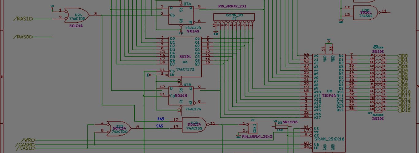
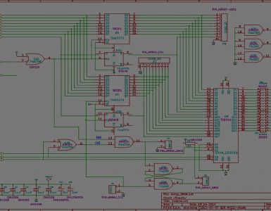
An old design can be seen here:
https://www.sensi.org/~tnt23/megadrive/index.html
I am now going to use slightly different chip – Atmel ATmega2560. It has 256K of flash memory – a bit too big for my code, but may be handy to store some short floppy image, like custom bootloader or minimal OS floppy. This new chip also has more than 80 I/O pins so CompactFlash support can be done, too.
There will no longer be no dedicated DRAM chip, I hope to interface to 72 pin DRAM PC modules instead. At 5 volts the MCU will run at full 16MHz (twice as faster as now), which hopefully will shorten overall ADF loading and conversion time.
I’ve also got different LCD to be considered, 132×64 pixels. I’m still undecided with it as it can be rather slow with its I2C interface. Maybe some other ‘parallel bus’ LCD like 128×64 can be used. This will for sure require to rework all graphics like icons and buttons.
Of course, all these changes must find their way into schematics first.
Wow. Do you solder/plan to solder such huge surface mount parts? I struggled a little bit with my 8-pin sm fram!! 🙂
Heh. You have it inside the amiga drive bay. Great idea!
If you don’t mind me asking, where’d you get your expertise with this stuff? School? Job? DIY projects like this?
Big-pin devices have always scared me. Lots of stuff to worry about. I’m going to interface a serial LCD to my project after I get the basic stuff working. Its a 2 row x 16 character LCD. Nothing fancy, but it will add a new element. Since its serial, the interface is great. Literally just serial-input, 5v, and GND. Love it. Only requires one pin off my SX.
I haven’t entered the kid-phase of my life yet, although I’m not terribly far away. I have a close friend who has two kids, a girl that’s 2 and a new boy thats about 4 months. I’ve heard plenty of stories, and I’m looking forward to entering a different chapter of life.
My interest to digital electronics and microcomputing started in high school, this was the end of 80s. In Russia we had to assemble computers for ourselves, first different i8080 homebrew apparatus then numerous ZX Spectrum clones. Nice playground to get some practice with electonics and soldering and programming also.
Nowadays I use to solder only relatively small parts, like registers and MCU. These have their pins spacing like 1.25mm and 0.8mm, this can be handled with some nice soldering tip and a steady hand. With spacings of 0.5mm it becomes rather tough. When dealing with 0.5mm chip at one of my side projects, it was clearly easier to have them soldered for me, the same way I order PCBs.
I too prefer simple things. An old Nokia LCD was used in floppy emulator just because its SPI interface required only three wires (well, actually four, with Chip Select signal). The new LCD attracts me with its 2 wire interface, but it is really slow. You almost always have to pay for something.
These serial LCDs are cool. I got one from http://www.crystalfontz.com to be used as a quick and cheap solution for debugging our software running on an embedded Linux/ARM platform where there were only 2 serial ports available. Speaking of both LCD and MCUs, sometimes it is worth getting one of those development kits that feature MCU of your choice, an LCD and a bunch of connectors and buttons. Like this one: https://www.olimex.com/dev/avr-mt128.html. My favorite local store has it for $60. Used it to interface to GSM modem.
Kids are fun, and they also grab a significant part of your time, life and room space 🙂 Difficult to stay up-to-day with your hobbies you know. My sister also has a girl aged 1.5yrs and studies at the same time. A real challenge I must say.