For the past month or so, I’ve been working on a project to modify an existing Logitech C920 webcam to accept modular lenses and allow for greater working distances but still have high magnification. I’ve got inspiration and parts from a few different sources.
The goal of this project is like many others: to have fun and learn! I already had a C920 web camera, and could really use more magnification when soldering. I also am a photo buff and own several Nikon lenses which I’m thrilled to be able to attach to this! I will probably buy a real microscope, but this was fun to do!
Contents
Sources and References
- This site at Operational Smoke blog talks about modifying a Logitech C270 to create a DIY USB Soldering microscope. This idea is fantastic, but the plastic case while being done in true hacker fashion just feels less polished than it could be if we just had a well-designed metal case. See next bullet point.
https://operationalsmoke.blogspot.com/2014/05/diy-usb-soldering-microscope.html - This blog out of Lithuania details someone, Saulius Lukšė, who did exactly this. He created a custom black anodized aluminum case for basically accepting the guts from a dismantled Logitech C920. The case is SUPER high quality. Cost $70 USD + $1 2-week shipping from Lithuania. Don’t forget to order the IR-blocking filter and the C->CS mount adapter.
https://lukse.lt/uzrasai/2013-07-modifying-logitech-c920-to-for-cs-lenses/ - Here is Saulius’ personal site where you can actually order items.
https://www.kurokesu.com/shop/diy_kits/KITC920 - Besides ordering from Kurokesu, I also ordered a few items from Amazon Prime:
- A ring light to get focused light on our subject: Fomito 48 Marco LED Ring Light with 8 Adapter Rings
- The adapter to convert CS mount to Nikon: Fotodiox Pro Lens Mount Adapter – Nikon G (FX, DX) Lens to C-Mount Cine & CCTV Camera Body w/Lens Aperture Control Dial
- A sensor loop to clean the dirt which is now on your C920 sensor: Carson SensorMag 4.5x30mm Camera Sensor Magnifier
- Small wire for the USB connections. You obviously don’t need 1000ft. PCB Solder Green Flexible 0.25mm Dia Copper Wire 30AWG Wrapping Wrap 1000Ft
- Really great wire strippers here that support 30awg: Klein Tools 11057 Klein Tools-Kurve Wire Stripper/Cutter, Blue with Red Stripe, 20 – 32 ga
- A cheap 50mm lens. This lens stopped focusing the day after I bought it. It feels like a high quality lens, but there’s definitely problems with it. I’m not linking to it because I really don’t want you to buy it. It was the Fotasy L5014 50MM F1.4 TV one.
- I also used this video on youtube to help figure out the initial screw locations: https://www.youtube.com/watch?v=94lDYZgihT4
Disassembling and rebuilding the C920
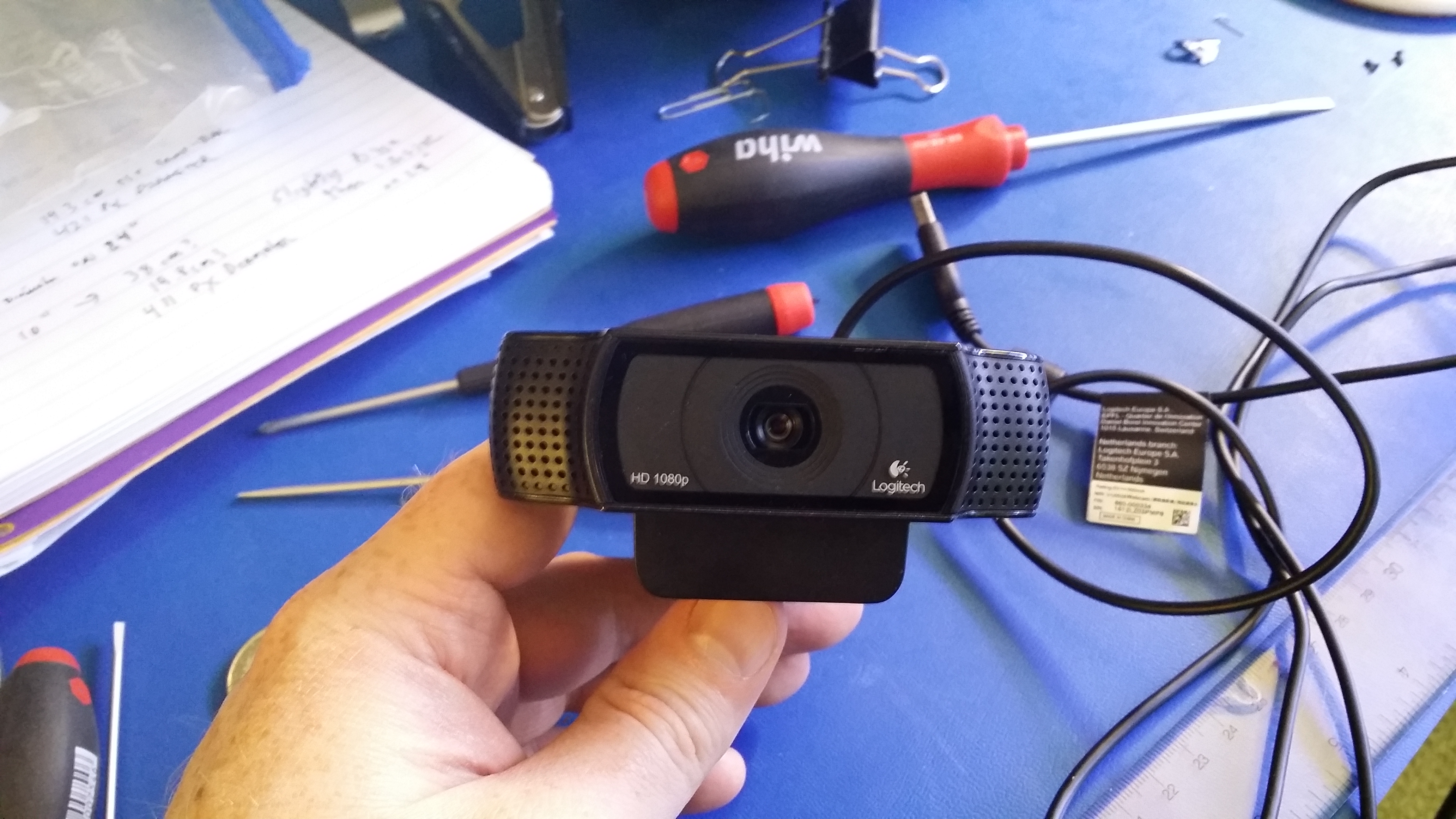
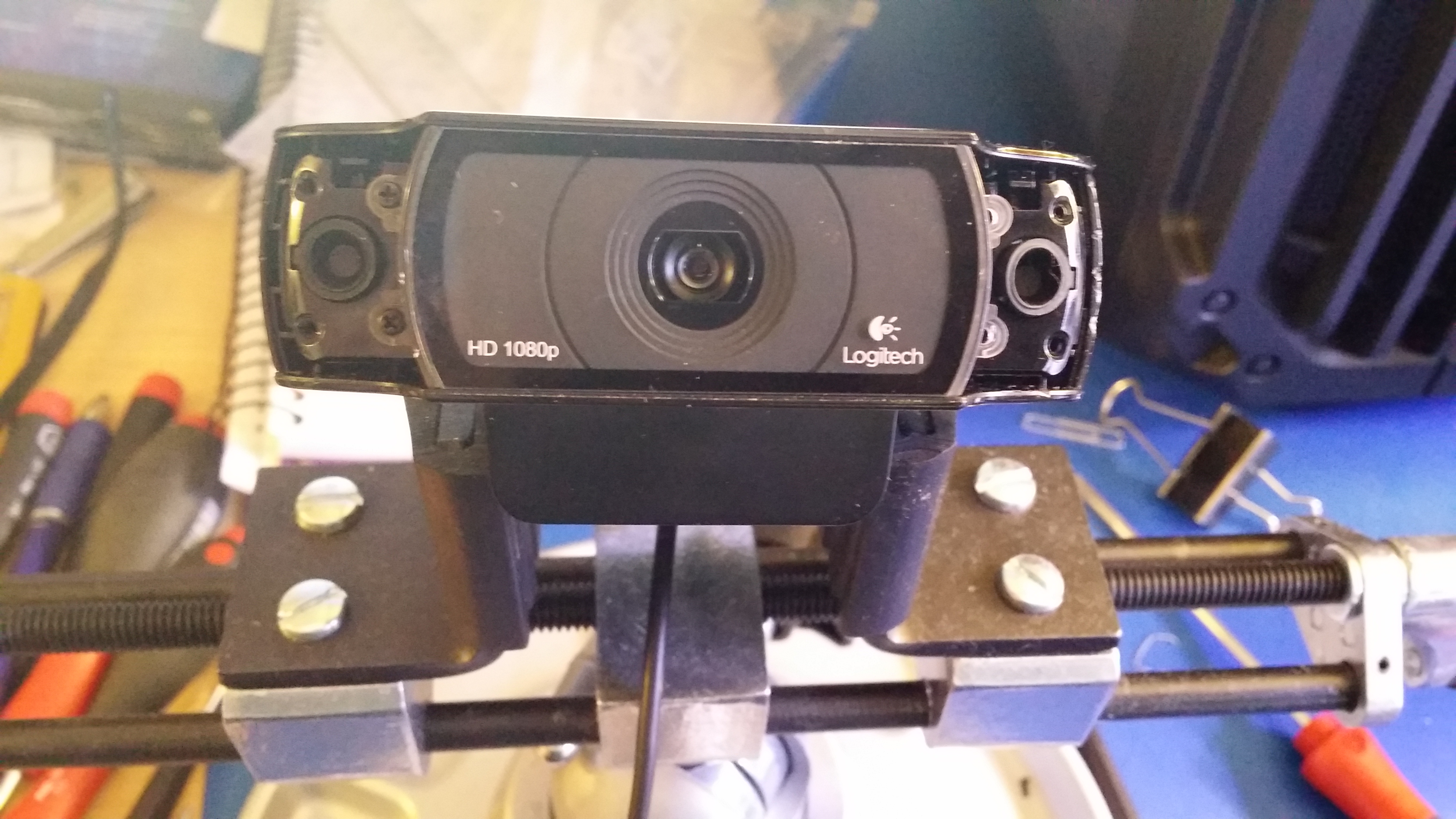
First, we start off with the essentially unmodified original Logitech C920 webcam.
Then we remove some (4) screws hid underneath TWO stickers on the bottom of the unit.
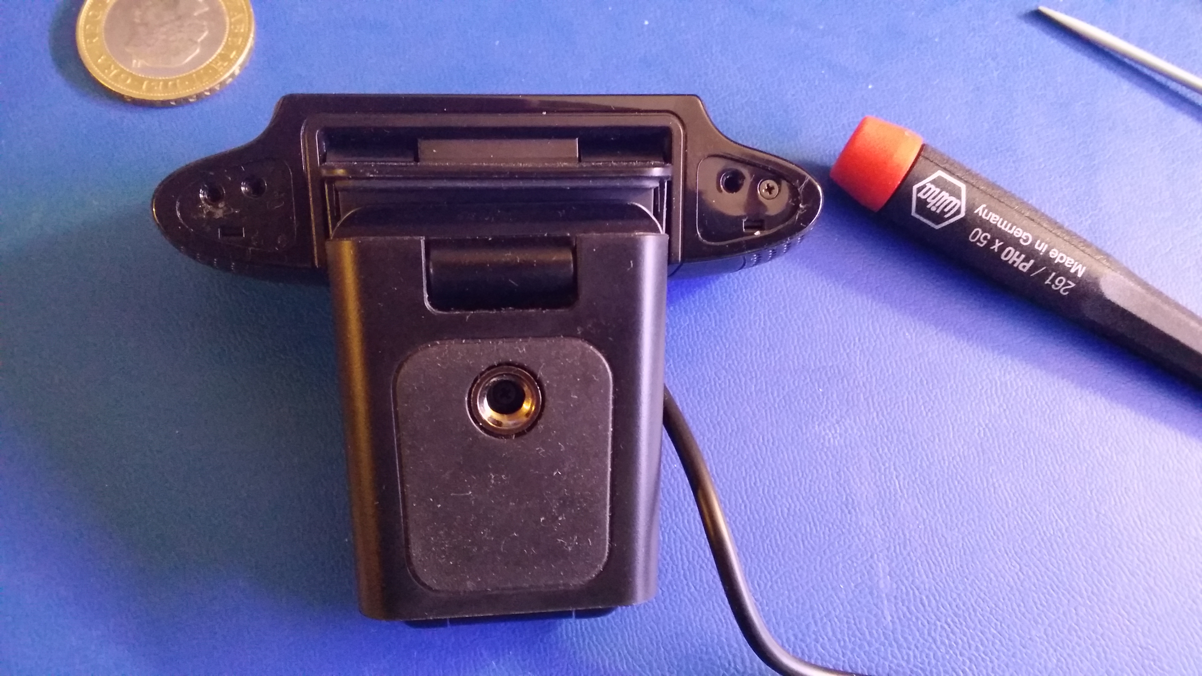
And then it looks something like this:
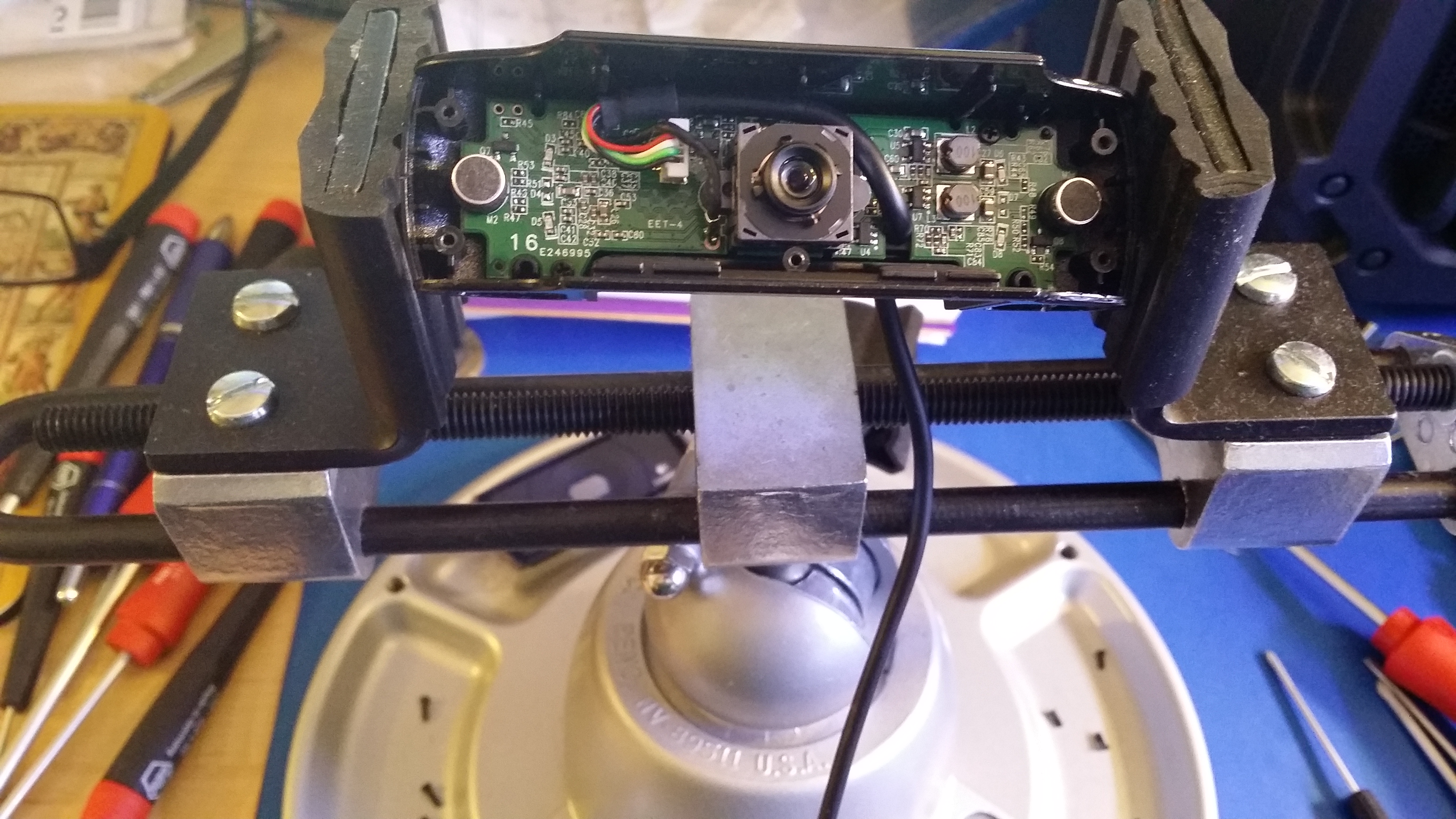
In the above right picture, you can see the existing autofocus lens in the center, with the two microphones on either the extreme left or right of the board.
And then, after removing the USB cable, removing the autofocus lens, and soldering (5) USB wires onto the circuit board in different places, this is what it looked like.
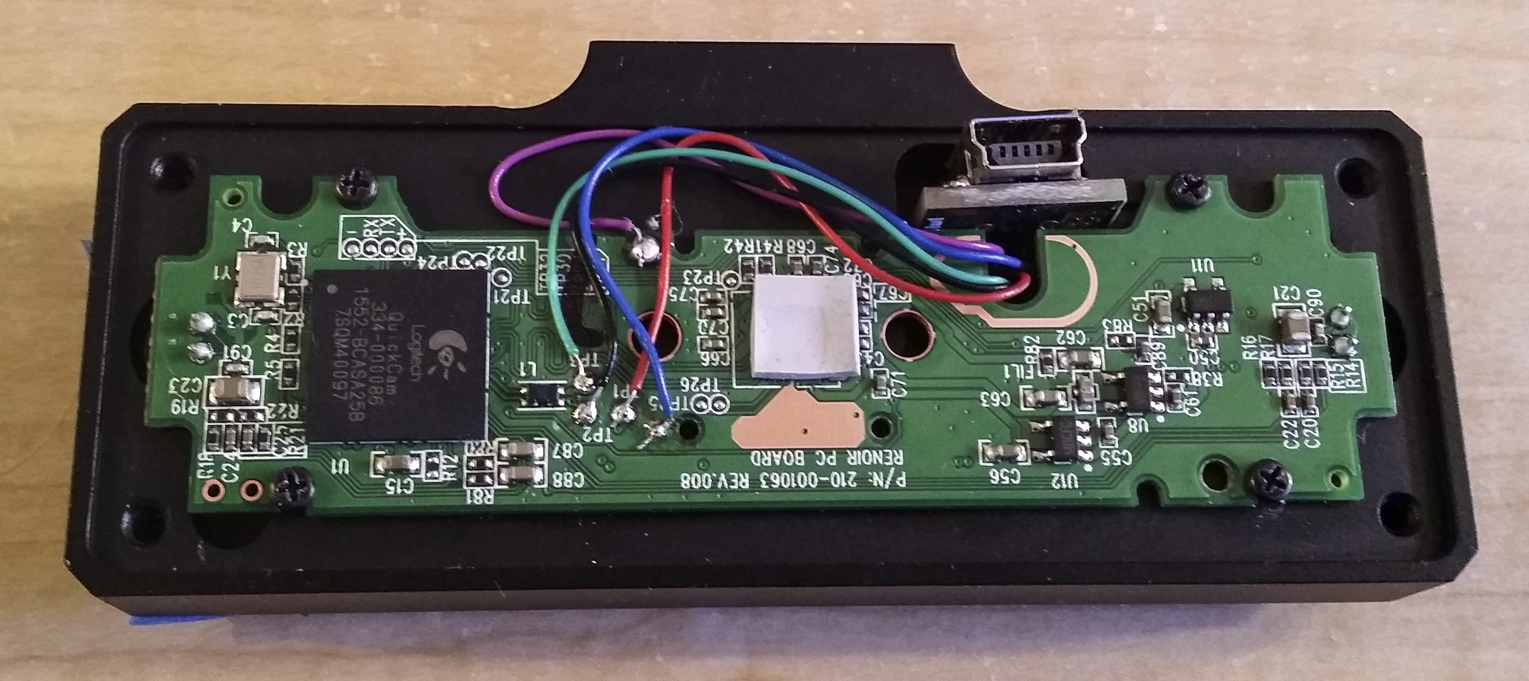
Between the video and the rework instructions provided at Kurokesu, I found it relatively straight forward to do this.
The tricky parts are:
- Making sure you have small enough wires. You probably can’t tell but these wires are 30 gauge. They really need to be somewhere around there for the case to close properly. I linked the exact wire I purchased up in the Amazon list. You of course need a way to strip those wires, too.
- There is a manufacturing defect with the screw-hole that accepts the screw to hold the USB connector in the case. I fought with this b*tch for an hour or so, and while I got it mostly tight, it’s a real pain in the butt. Outside of trying a small screw or something from the hardware store, I have no idea how to make this easier to do.
- You need to scrape the soldermask off the top layer of the PCB to expose a (ground plane?) from the layer underneath, and you need to solder a wire to that plane. This requires a sharp xacto knife and some steady hands. Accidentally cut a trace, and you’ll be fixing your PCB.
- If you haven’t done stuff like this before, this project might be on the edge of a beginner’s skillset. I’ve got moderate skills.
Finished product
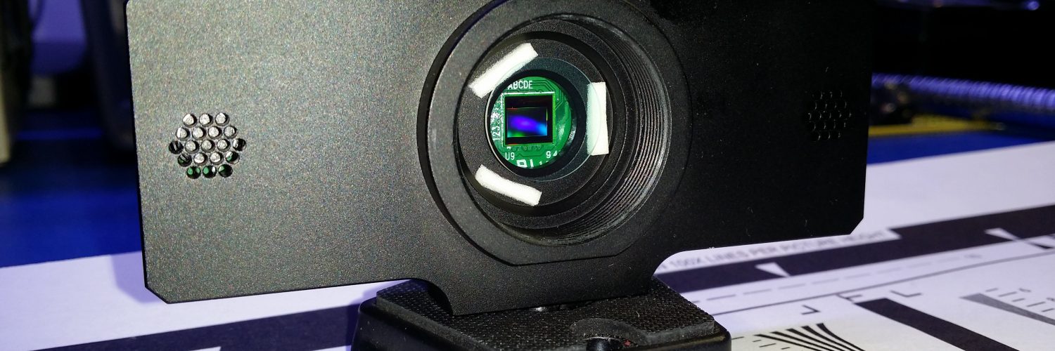
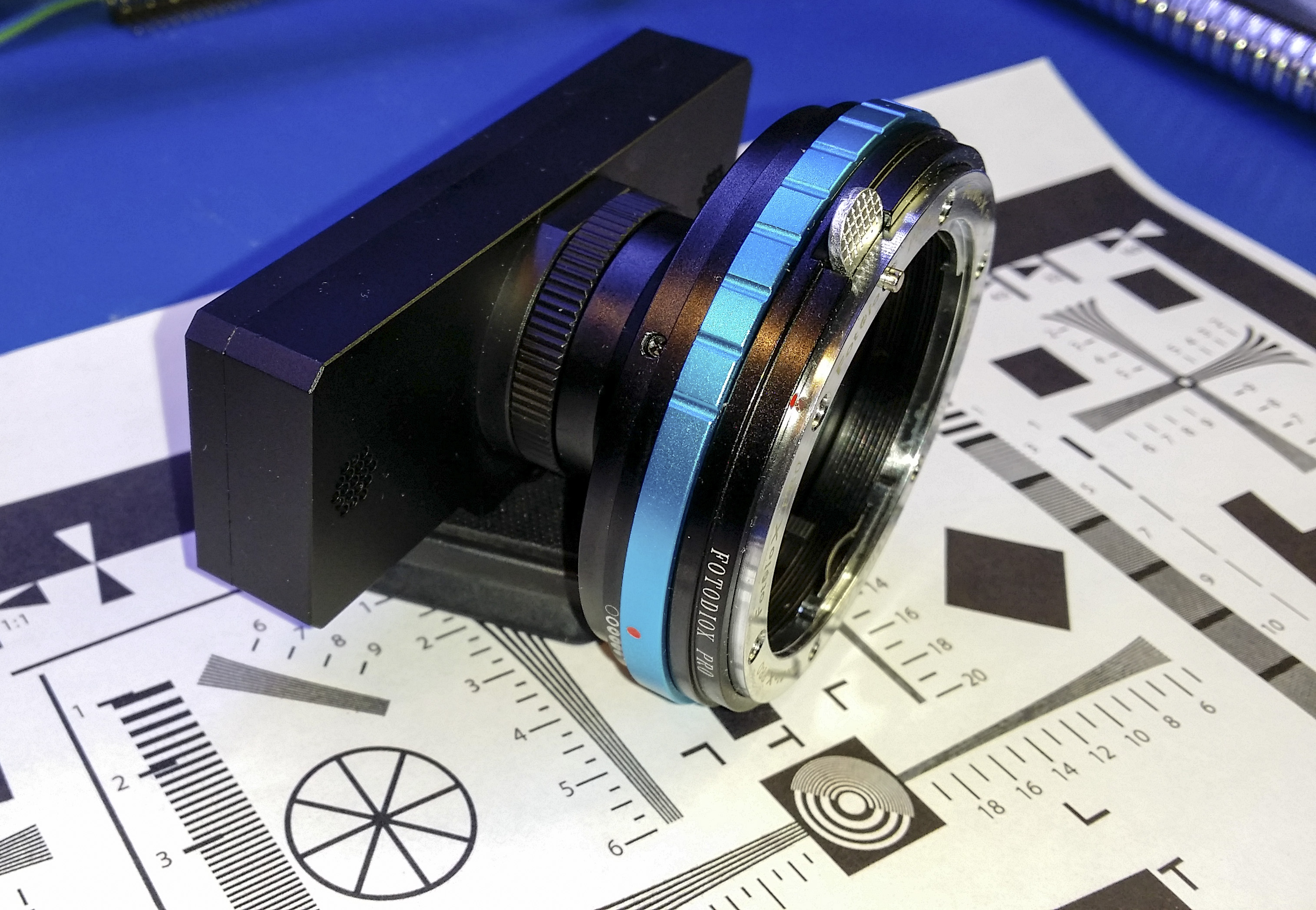
Some finished pictures of the unit with and without lenses are below.
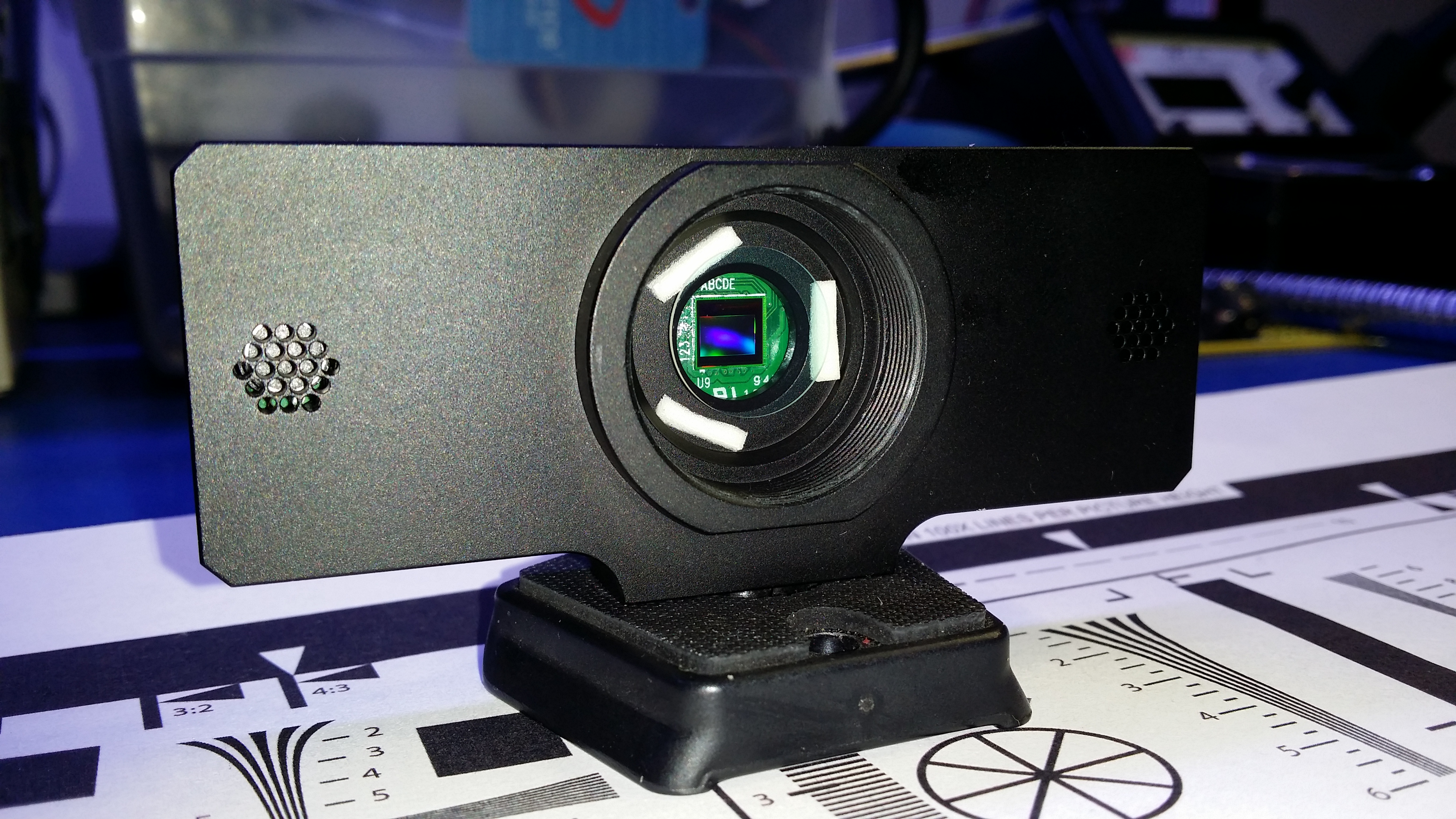
Notice the sensor is visible inside. The sensor is 4.8mm x 3.6mm, or 6mm diagonal. This is normally referred to as a 1/3″ sensor and likely has a crop factor of around 7.2.
You can also see the double-faced duct taped IR blocking filter which is clear above.
Below shows the Fotodiox adapter which allows me to connect my existing Nikon Lenses. The adapter is reasonable quality and works exactly as it should.
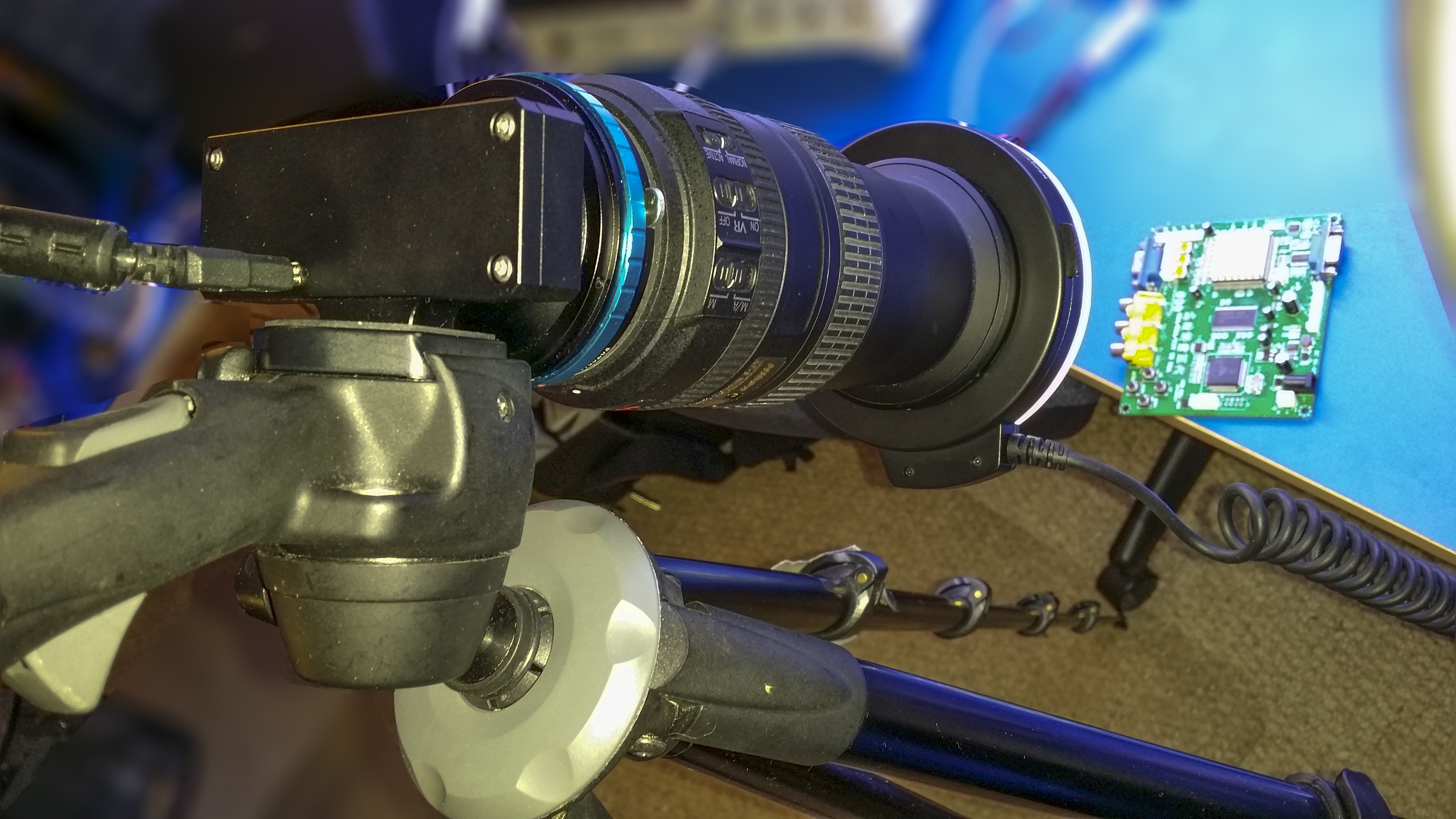
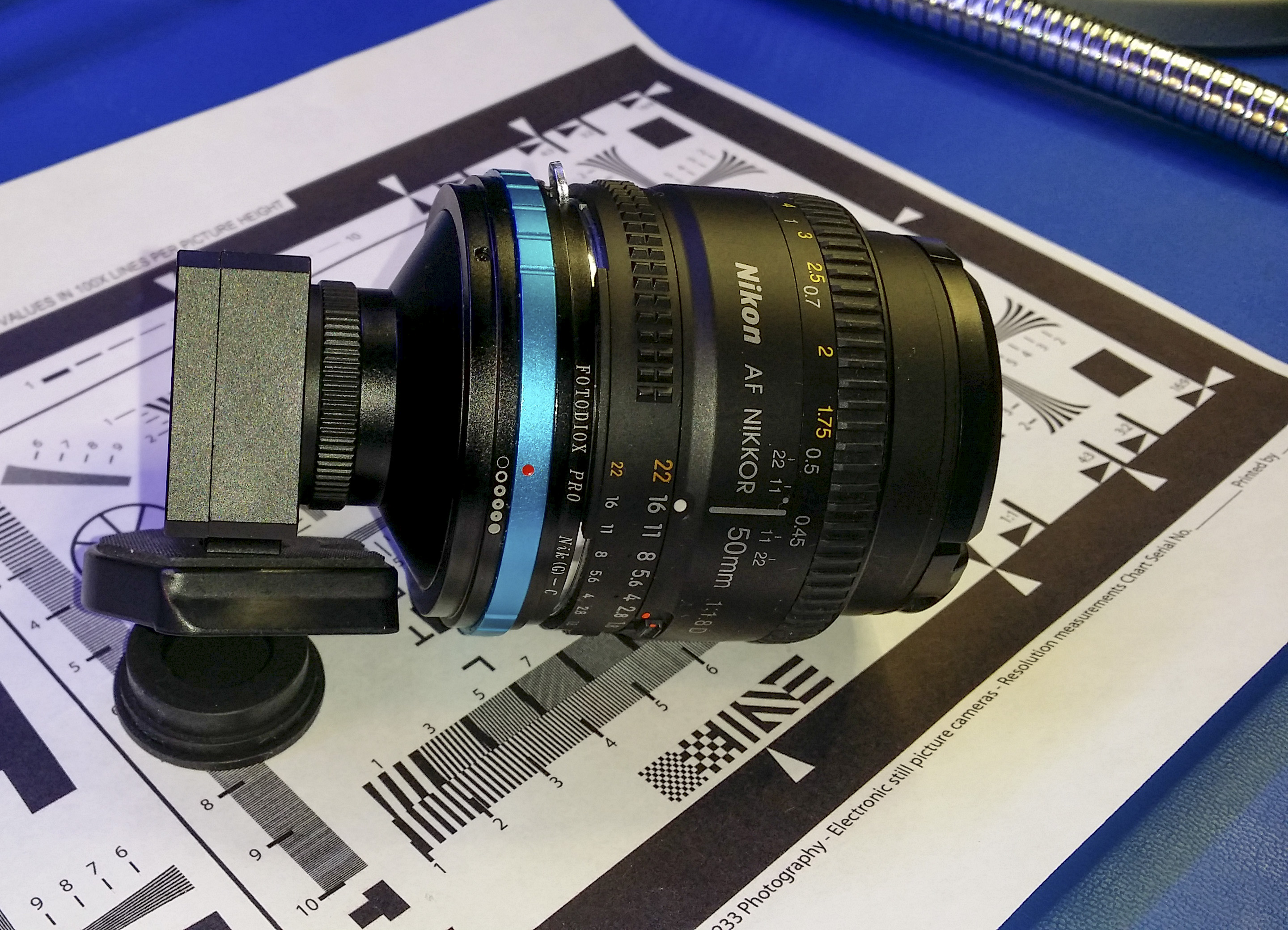
Below you’ll see what the setup looks like with my Nikon 50mm F/1.8D lens.
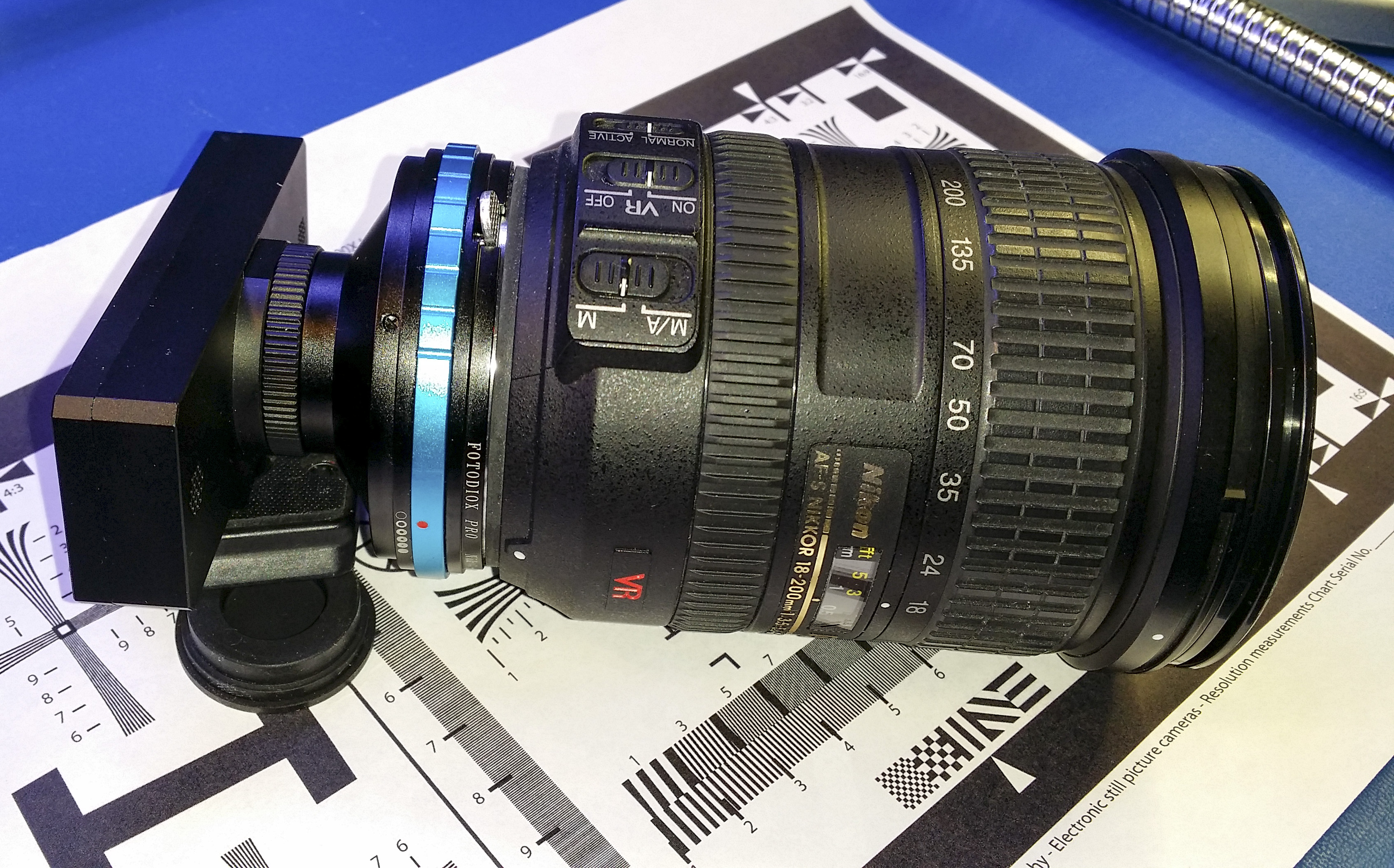
I think this image below is badass with my Nikon 18-200mm lens attached. Now we’re cooking with gas!
Images through the C920
I’m still trying to figure out and optimize this setup for the best image quality. This is a work in progress, but here are a couple to start with
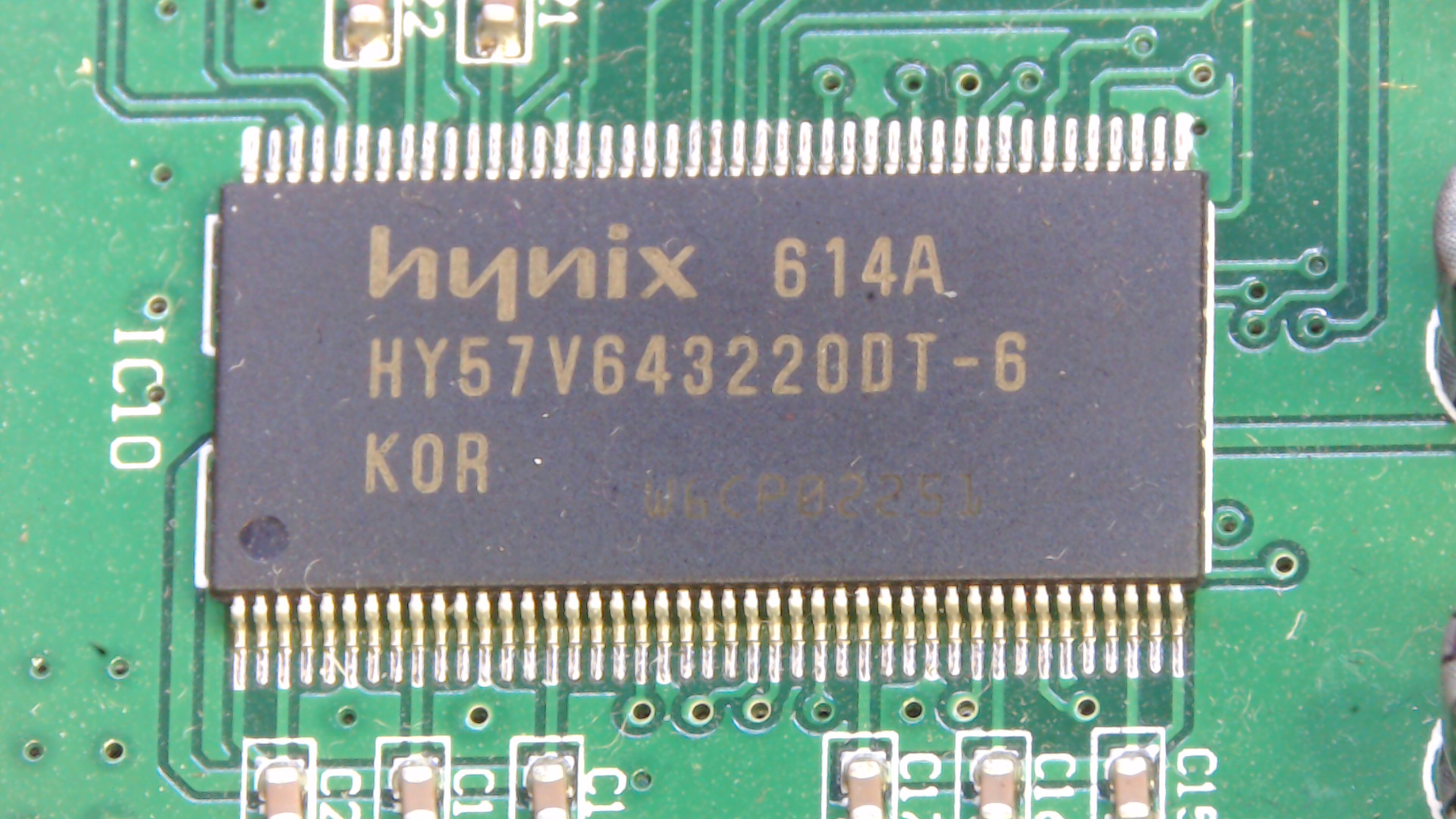
The image below is at 18mm and a working distance of 10 inches(25cm). I’m using the definition of working distance to mean from the front of lens. (Farthest from the body of the camera)
To give you an idea of magnification, the hynix memory chip you see pictured is 22mm wide.

This image below is at 100mm and a working distance of 15″(38cm).
The image below is at 200mm and a working distance of 15″(38cm). I could actually reduce the working distance here and achieve higher magnification levels. This lens focuses closer than spec (spec = 1.6m) with this camera setup than with my Nikon D300.

(A video coming soon)
Mounting concerns
I’m currently using a half broken tripod that I bought years ago. I have to buy a new tripod, but I have to come up with a better mounting solution. I’d like the camera more or less directly over the subject, but how do I manage to mount and still be flexible enough to move the camera around?
Saulius recommended a 7/11″ Magic Arm and a C clamp. I still need to investigate this.
Practicality, image quality, results
Because I already have the lenses, I might be an exception here. Maybe this project only makes good financial sense if you can find cheap, quality lenses. But the Fotasy 50mm that I tried from Amazon was pure junk. It’s not lost on me that I’m using a $600+ lens here for this project. This was a fun project. I’m still trying to analyze the results. Due to the magnification on the monitor, I can have this 22mm chip appear to be the full width of a 24″ monitor, or even bigger without exceeding the initial image resolution. The overall magnification of the system seems huge!
Did you buy the IR high or IR low pass filter?
IR Low Pass. We want to block IR. Your pictures would be purple without it. You want the low
frequencywavelength light (visible) to pass, and the higher (infrared) to be blocked/attenuated.just finished making mine today, with my 50mm nikon lense i seem to have to have the working distance of 3 feet to get a clear picture. otherwise the image is blurry.
Congrats man. Not too hard of a project. Did you use the kurokesu case? Is that USB board screw a big pain in the butt or what?
What do you think about image quality, etc?
I’m curious how well this works with video, on things moving? For example, I’d love to see video of this on something moving, say an item on a turntable or interviewing a person. I’m debating on playing with a few of these for Canon/Nikon upgrade, or with the C/CS mounts.
However, nobody seems to show any video done with the upgrades. I’ve been looking for video done off of one of the case upgrades done by Saulius Lukšė, and can’t find anything other than the videos he’s made on how to make them. I would love to see some side-by-side comparisons and tests of the standard C920 and the upgraded versions–to see if it’s really that dramatic of an improvement.
I would like to see if this makes podcasting webams better, cheaper….or should I just bite the bullet and get a couple Nikon 3200’s, or Canon T5i’s? I’d love to adapt the C920’s.
If you have seen some videos as described above, I’d love to be directed to them!
Thanks!
Michael
Michael,
I think you’re misunderstanding the primary purpose for modifying these cameras. You wouldn’t want to interview a person through this…..definitely not. The main purpose of the modification is to extend the working distance while not losing apparent magnification. You see, a regular C920 could be used to do very fine work if the camera was a couple inches away from the subject. This is fine for somethings, but other things, like soldering requires enough room to get a soldering pencil in there. But as soon as you move the camera that far away, now everything is too small to be used for that purpose. This allows you to modify the camera to accept longer lenses that can accommodate this type of application.
There are other applications, like Astronomy, where you’d like to remove the normal IR filter with the express purpose of capturing other wavelengths of light.
If your primary purpose is to record HD video for a podcast or something, you should stick with off the shelf cameras and lenses. This is not for you.
Hope this helps!
Keith
Would there be many advantages of using the C920 over the C615 webcams for this, disregarding the case of course. Im mainly interested in a comparison of the webcams and how they would work as far as specs.
Would love to try this with a body from an old canon camera and just hollow out the body and use the fd mount of the camera and stick the web cam inside.
Was just wondering if the added expense of the C920 over the C615 would justify the cost.
Surely your time is worth more than $25. Which is what the street price difference is on those models. For these types of projects,I always go with the “better” option, it almost always pays. If you build it with the cheaper one, and get mediocre quality, what’s the next step? Wondering what the c920 looks like?
Hi there,
I have used the C920 on several occasions to tape Tennis matches, i.e. I have them mounted on the ceiling of indoor courts. However, the biggest obstacle that I have yet to overcome is the depth of field. The nearby and far away players and logos etc on the courts are out of focus with the standard setup.
I am in general relatively new to this and all the terminology of optics. As far as I understand it, playing with aperture in a lens that can actually do that would to the trick for me.
Does anyone have any experience in this regard with the herein mentioned custom setup?
Many thanks in advance
Christopher
Generally speaking, depth of field is controlled through the size of the aperture. The smaller the aperture (so the bigger the f/number), the more things will be in focus. Landscape photographers use high f-stops, and you’ll see them shooting at f/11, f/16 and beyond. They want the whole mountain range etc in focus. Just remember that with smaller apertures, you get much less light in, and you need to compensate using the normal exposure triangle rules. Shutter speed and ISO. With these web cams, I can tell you what happens is that they jack the gain (iso) up, and then electrical noise produces a pretty crappy image.
Smaller sensors, like these ones, do have an inherent advantage. It’s easier to have a high depth of field. They struggle with subject isolation which is normally desirable in (single shot) photography.
I do have an on-lens adjustable aperature on one of my Nikon lenses. Stopping down (increasing your f/number much past f/8 or so) definitely doesn’t work inside with limited light, although I added a ring light for specifically this reason.
Have you already built this? What available light do you have? What lenses are you using?
Got mine working, I put a C615 in an old Canon AV-1 body, don’t have to mess with lens mounts or anything.
Have you come across a good software package for viewing or working with the cameras.
Nice Job, Jeff!
Not really, I was using VLC or the logitech software. It’s simple enough and basically works. Haven’t used it more than a couple times since I built it, however.
I used Contacam by Contaware for the most part. The software is free and you can donate if you’d like. I did since the programmer is really great with custom issues and questions.
Saulius was great to work with also, so I wound up buying the case. At first I was going to use another design with the 700 case and thinking to machine though my brother also convinced me not to since the time to machine with materials (unless I wanted to machine myself) was better for me to just buy from Saulius. Saulius noted also that using the lenses that are not designed for the size of image sensor chip on the C920 will make macro or close up images blurry.
We also wrote about being able to use the auto focus and he has a system that does that operation too. I didn’t get to the point of buying a C/CS to Nikon mount with AF so haven’t worked on yet.
I have a few older manual Minolta lenses and a body that I planned to use on this first system for security more-so, so photos up close weren’t planned anyhow.
The screws are a pain, though do-able. Maybe you can drill out a little larger diameter if you’re having issue.
I actually am about to pull mine out to see what the frequency range is as I was hoping to find the range online somewhere and have not yet… so will see how operates as a spectrometer with the LED’s and emitters I have.
Firstly you did a great job. Thank you for sharing this stuff.
I am working on a PCB optical inspection project. We have to detect defections and classify it. Also we want to define the components in PCB.
Have you done OCR before you attach the lens? For C920, does OCR work properly without the lens or is it necessary to have a lens modification for this purpose?
Thanks in advance,
Şerefcan
OCR on a non-text object seems odd to me. Is the plan to read in the silk-screened component identifiers? Like C1, C2, R1, D1, etc?
You need SOME lens on the C920 in order for this camera to focus. You either need the built-in lens that comes with it, or you need to attach something externally like I’m doing here.
We have to do character recognition on chips like hynix 614A memory chip you mentioned above. So the photos we captured should be clear enough that we can read the texts on the elements of the PCB circuit.
I wonder if we can read the text on the chips without attaching the lens?
No, you cannot focus the camera properly without some lens!
Proper OCR usually dictates an effective DPI of 300-400 pixels per inch.
“Tesseract works best on images which have a DPI of at least 300 dpi”
ABBYY: “For regular texts (font size 8-10 points) it is recommended to use 300 dpi resolution for OCR.”
I know this isn’t exactly a scanned text document, but the amount of entropy per character likely has to be the same to make the right determination.
We decided to buy a camera with lens modification as a result of our researchs and your recommendations. However, this camera will have a manual focus.
Our system will be in the form of a fixed box. Once we adjust the manual focus according to the system, can we get clear pictures while using it in the same light conditions? Or, if we take an autofocus camera, which mm values should we prefer?
This is my Day microscope for electronic.
https://youtu.be/Ls-dqh6yxw0