Background
As some of you may know, I’ve been working for awhile reverse engineering a DataFlyer 500 SCSI HDD controller from the 1990s. While I’ve had a working GAL replacement for the PAL for some time, I always wanted to do a side-by-side validation where I pump the same inputs into both chips simultaneously and then compare the results.
GAL Verifier setup
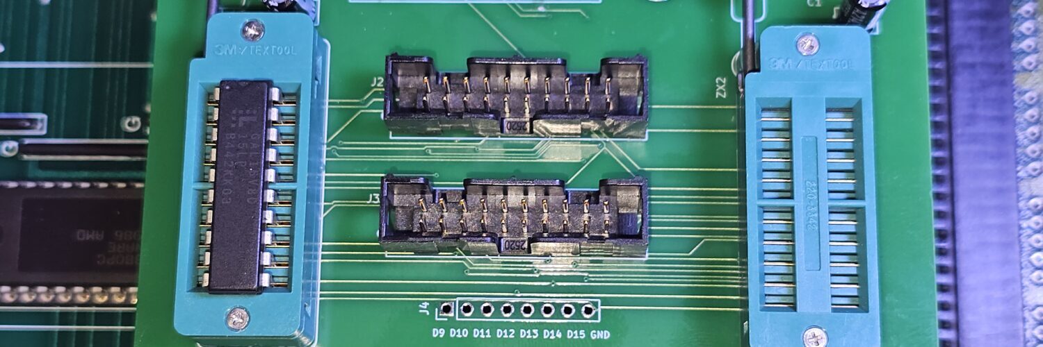
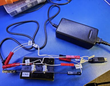
Here’s the custom PCB I made to perform this task:
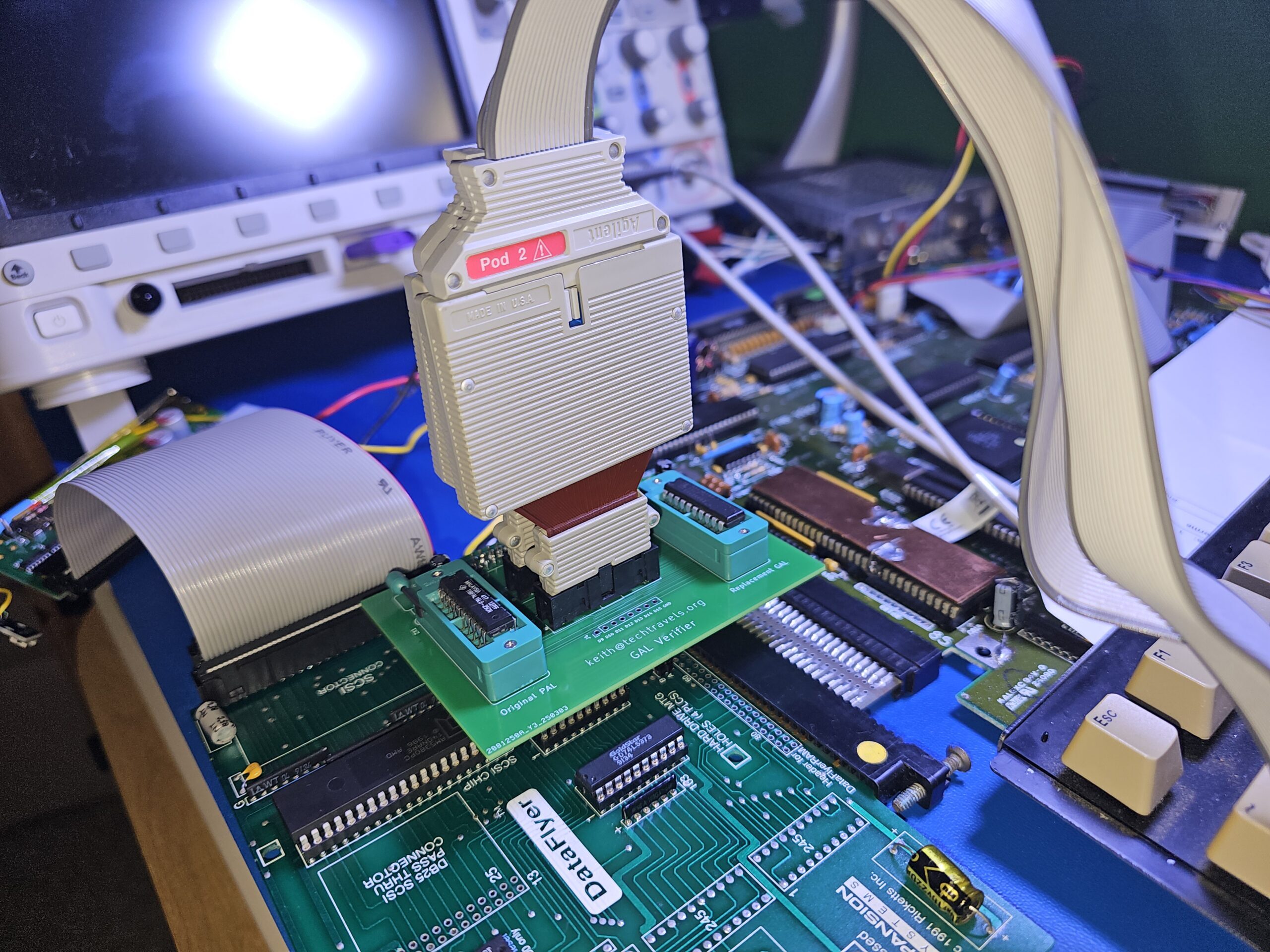
The left hand side ZIF socket contains the original dataflyer PAL chip, and the right side is my GAL replacement chip.
Those center two pods go to an Agilent 16900A logic analyzer using a 16910A, running around 1ghz (half-channel mode), even up to 4ghz for the timing-zoom sections! Yes, that’s overkill for the application, and no I don’t care. 🙂
The observant of you might also catch that I replaced the factory crappy dual-wipe sockets with Preci-dip gold’s. So much better and more secure fit!
The Test(s)
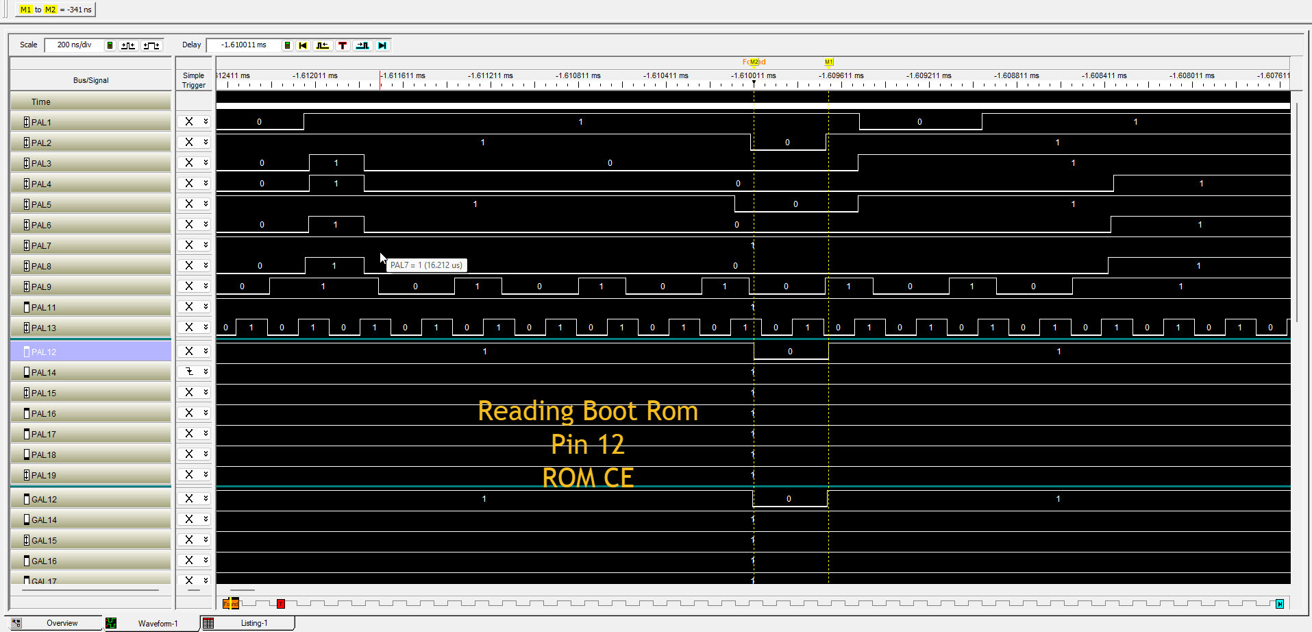
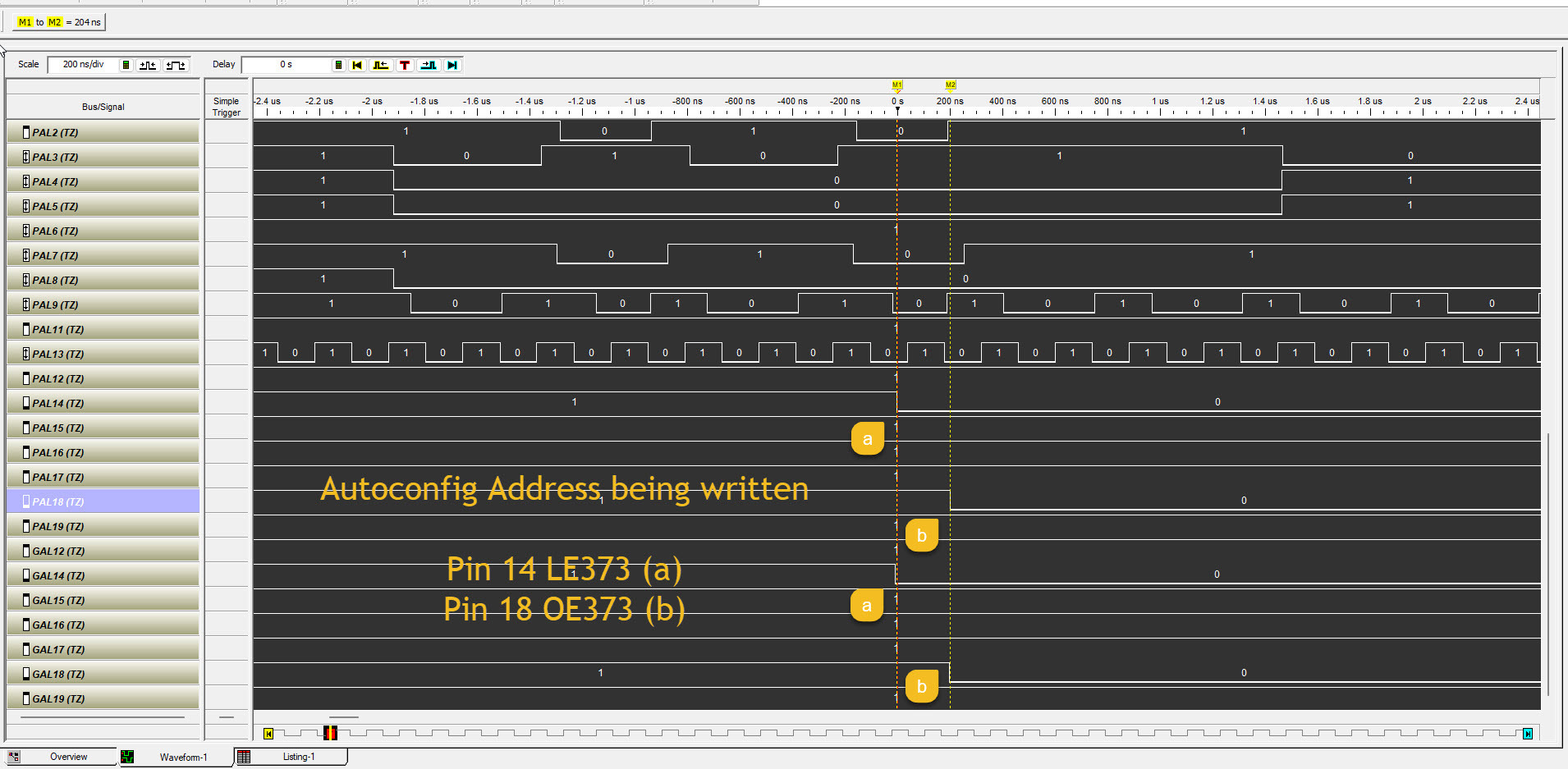
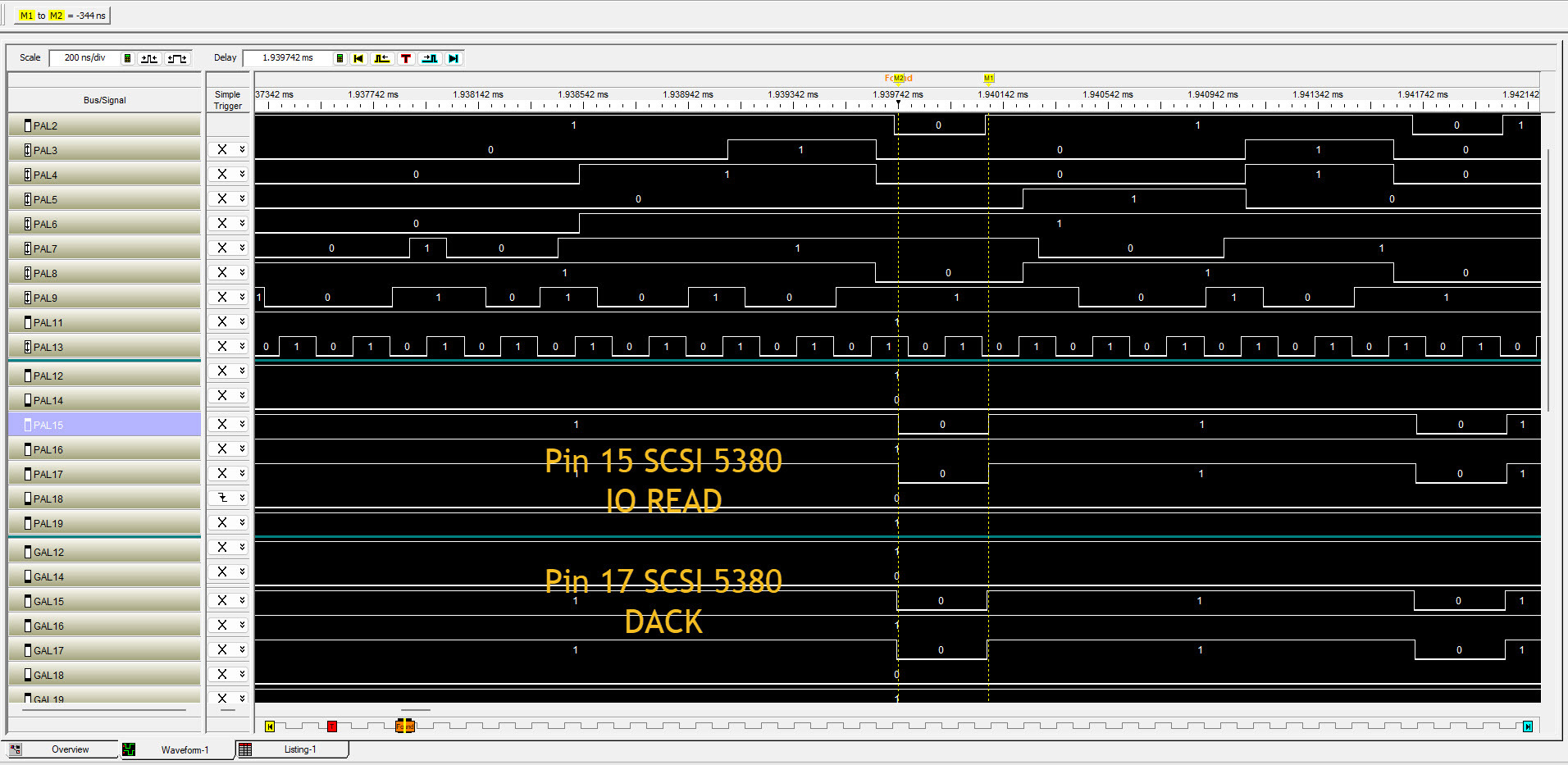
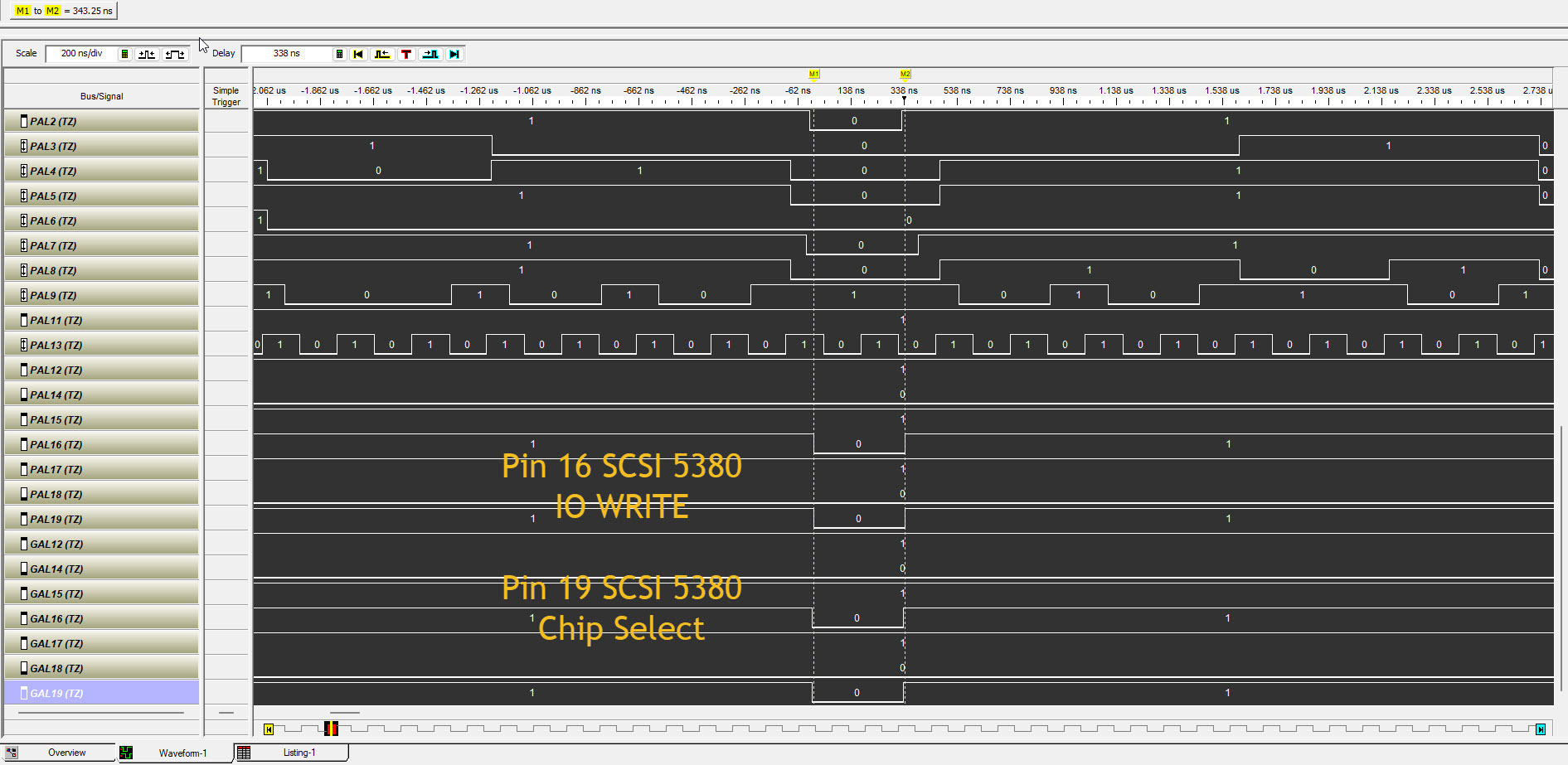
Using the system as normal during boots, reads/writes, etc I triggered off of things like an initial boot rom read, the newly assigned autoconfig address latch, and other output pins and set the logic analyzer to record. It captures for less than a second of activity, and then displays it in a waveform display. The waveform has one signal per row, with the first (18) pins of the PAL, which includes the input pins (1-9,11,13) and then the output pins (12,14-19). The GAL output pins follow. When looking at the results below, you should find the pin of interest, say Pin 12 and look at the waveform, and then skip down to the GAL12 pin, and compare them. More details on how to compare them, below.
Heisenbug
Using the GAL Verifier at all introduces delays that wouldn’t be seen if the new GAL chip was simply plugged into the board. Measurement error and artifacts show up at the speed in which we are measuring, so it’s quite possible that the results are BETTER than what you’re seeing here. For instance, the distance on the GAL Verifier between the two ZIF sockets likely adds about 500ps difference to the arrival time of the signals to the GAL, which delays the output.
Results
In a perfect world, the output waveforms from the GAL would match the PAL precisely. A 100% match isn’t required for operation, thankfully. You see the GAL16V8D-25 that I’m using, is faster in some ways than the TIBPAL16L8-25CN that I’m replacing. This causes the output waveforms to shift left, because the GAL is reacting to the change in the inputs faster than the PAL does. The pulse width is generally within +/- 0.5% difference, so it’s close. The reaction times including the propagation delay through the GAL are generally 5-7ns faster. Dividing, say 6ns, into the nominal pulse widths of around 344ns gets us about a 2% difference.
All this to say: my replacement GAL is an extremely close match to the original, and I haven’t seen a single instance where there’s a functional difference.
Comparing Waveforms
With logic analyzer captures from both the PAL and GAL, comparison comes down to checking if the GAL behaves logically the same under identical inputs. Look at corresponding output pins (e.g., PAL12 vs. GAL12) and compare key characteristics:
-
Edge timing – Are rising/falling edges aligned within a few ns?
-
Glitches – Do either outputs show unexpected transitions?
-
Pulse width – Are high/low periods similar in duration?
-
Propagation delay – Does the GAL react faster or slower to input changes?
-
Final state – Are outputs in the same state during stable periods?
Some timing differences are expected, especially since GALs are often faster. Focus on functional equivalence, not perfect alignment. Measurement artifacts and the test setup can also introduce small variances—don’t chase ghosts.
More reading
If you’re interested in more posts about the reverse engineering PALs, click here.
If you’re interested in more commodore amiga posts, including dataflyer-related items, click here.
Next Steps
I haven’t done a great job of making downloads available with my work. There’s a few reasons for that. Some of it is related to lack of time, organization, place to put it, etc. Other thing is that I’ve lacked confidence, up until now, that this is a really a working solution for all cases I can see. I’ve created a github project, and will start uploading soon. (July 2025). Bug me if I haven’t done this.
There is still the DTACK02 PAL, which is used for IDE support, for these cards that I want to reverse. I have a fair bit of work already put into that one. That one may not have any latches or state and be easier.
I also have half a mind to recreate a SCSI-only board with an ebay replacement 5380 and my gal. I’d probably change most things to surface mount, if I can. If you need to ask a question like, “what’s the point?” you really haven’t been following the purpose of the blog. IT’S THE JOURNEY MAN!

Add comment