Welp, I’m having trouble tweaking my existing SX code. If I modify the timing of the current code, I’m getting all garbage output — even adjusting small amounts to one side or the other, produces much worse results.
With some help from Guenther and others at the Parallax forums, I’ve pretty much determined that writing SX code that has to deal with two interrupt sources is hard. The two sources in my case are the edge-event, and the rollover event. I’ve long thought that I’m missing edge events because I’m in the middle of an RTCC rollover. I’ve actually seen this happen, but because of the speed and the lack of a scope that can store seconds worth of data — I really can’t narrow down why. Obviously, the timing is off.
A few people in the past have suggested I approach coding this differently than I have — and now that I’m getting more input, it really looks like there is a better method. This different method uses only RTCC rollovers, sampling the data at a high speed, and simply counts the number of rollovers between edges.
This seems like a better method. Even the SX manual suggests polling for detected edges instead of using the edge-detection-trigger method like I am now — exactly because of the conflicts I’m seeing.
I hate to go backwards here, but I’m going to rewrite the code from scratch. The only reason why I don’t like this method is when the next edge occurs, you get this onslaught (ok, either 1, 2 or 3 bits) of data all at the same time. What this means is that you are now working with two storage bytes instead of one. I’m not sure how well SX/B is going to be suited to this.
Another thing I’ve discovered through talking with other people, is that there’s another way of thinking about this problem. I’ve always considered an edge a “1”, and a HIGH a “0” — and this is very true. I’m now thinking about an edge as a BOUNDARY of data bits on the left and on the right of a certain number of place-holder 0’s. So really the data is defined by how many 0’s are in between the 1’s.
Before when I saw a HIGH after an edge, I “stored” a zero. But really, I don’t need to STORE it, I just need to shift left for every HIGH that I see. Sure, the net-effect is the same, but the implementation is a little different — and a little bit easier as well.
I should have the rough draft of the code written today.


Good luck!
In the meanwhile, here’s my progress:
https://milliways.chance.ru/~tnt23/pics/misc/megadrive.jpg
This clearly shows both success and failure of my idea of delivering MFM flow on-the-fly: note 0x44A9 instead of 0x4489.
Thanks.
I see you got DiskMonTools running. Is the Amiga actually recognizing your flow as valid disk data? And did you ever figure out the problem regarding that floppy.c encode routine? I looked at it pretty closely, and it looked ok to me. The decode routines are perfect. And really neat, clean, easy to read code. How are you generating the flow to begin with?
I just finished writing the 8th revision of the code. This time, instead of the falling edge triggering the ISR, I now poll a register that tells me whether an edge has occurred every 1/2 us within the ISR. This is a little different from just sampling the port every 1/2us, the SX mcu records that an edge occurred and then I have to manually reset it after I’ve checked it.
What this means is that possible conflicts between the RTCC rollover and edge-triggered interrupt sources are now gone!
I haven’t tried this new code yet, but it looks promising.
Its interesting that I really just put a “1” in the MSB for an edge, and then shift left for each 2us timeout period(ie a HIGH). Once I shift the entire contents of the low byte into the high byte, I transfer the high byte to the PC, and the next edge starts at the MSB of the low byte again.
I also now have much more granular control on what is considered an acceptable time for valid data. For instance:
I can consider 3.5us-4.5us to be a valid length for ’10’ combination, or a 5.5us-6.5us for a valid ‘100’ combination and so forth. Before, I could only regulate the period at which it sampled, but now I can define “acceptable” or “within range” times for the data.
This is useful because it seems that I have a lot of readings that come in shorter than the spec’d length.
Really my only concern with this new code is that the overall sync-to-edge timeout isn’t going to work……we’ll have to see.
Hi,
writing a bit late due to active weekend. Be prepared 🙂
The problem with the encoding routing (or so I think there is a problem) is that while encoding interleaved data bits, they simply OR it with some sync pattern, like 10101010 (0xAA). I’ve put some debug statements into my code that would produce MFM flow for my MCU (will explain it in a minute), and have been able to see encoded output it produced.
That is, if we have byte 0x89, we split it into odd bits (0000.0001) and even bits (1000.1000). With the original encoding procedure these bits get ORed with 10101010, giving us odd (1010.1011) and even (1010.1011) encoded bits. What may seem odd about these encoded bits is, of course, two ones in a raw which, if I understand the MFM encoding principles correctly, just can’t happen.
I think it is done so due to the fact that in emulator, there is no real PAULA chip, and therefore no real PLL circuts. So for the emulator to correctly decode MFM flow, you just have to AND the flow with 0101.0101 pattern, effectively leaving out sync bits we’ve introduced when encoding.
Thus instead of 0x4489 eye candy I’d get 0xEEAB.
I am only puzzled why on earth they bothered adding this 1010.1010 OR operation at all. Maybe there have been some idea behind it, but I fail to see what it can be.
Anyhow, the result of this encoding didn’t work for me, so I wrote simple ‘MfmFix’ routine. This routine would run upon what encoding routine produces, but will bring the resulting MFM flow to full standards compliance. Or I think so.
Now, to my MFM flow generator. Remember it is an Atmel microcontroller running at 8MHz, allowing for as much as 16 one-clock instructions per 2uS bit cell.
At first, I thought I could’ve come up with some brilliant code that would produce real MFM flow out of unencoded data. I had to throw the idea away after I’ve seen it is impossible to generate 0x4489 pattern this way just becase it had been chosen right for the purpose of violating the MFM encoding standard.
Then I rewrote the code so that it would simply output whatever MFM encoded data it is given. Hell, I have said to myself, I’d better load sector data from out there, create a real MFM track in RAM and then have my MCU spit it out precisely.
For test data, I have chosen a couple of sectors out of GODS1.ADF image. I have encoded them into rather odd track (sector 0, sector 1, gap), and this track is being outputted by MCU right into Amiga’s external drive port. (I have also to add some diode to the port so that Amiga would thing there was an external DF1: drive upon startup).
My A1200 won’t boot from it so far; I believe I have to get some ‘intro’ boot blocks (from Aminet) to put into sectors 0 and 1 of track 0 so that I could see if it would load and run.
But the DiskMonTools sees the MFM data clearly! It reads my fake track at once, and even reports the TInfo correctly (though the sector list is funny, being built of sectors 0 and 1 and 0 and 1 and so on). It even testifies the header and data are checksummed OK.
Neat idea with ‘running 1’. Leaving another interrupt source out probably will mean leaving out another source of problems as well.
I have found the SX forum at forums.parallax.com and am watching it intently. I like the atmosphere of brainstorming you guys have there, and hope to see you coming up with more success soon.
Wow! This is great progress. Good job. Just the pure fact that you are able to see the data you are creating get inputted into DiskMonTools is awesome. And if you got the header & checksum ok, you must be pretty close to perfect.
I figured that being able to boot from a mcu, or from memory, from your device is really the “be-all-end-all”, holy grail, etc of your project. If you can get it to boot, you would be pretty close to getting the whole thing working.
Yeah a ’11’ is definitely illegal. It’s always 10, 100, or 1000 followed by another 10,100, or 1000, etc.
No idea btw why their sector encode produces non-mfm compliant stuff. The amiga uses a little more intelligent process, where it looks to the bit to the left and the bit to the right, and add’s a ‘1’ where necessary.
I’m glad the decode process just throws out the clock bits, so for my purposes I can basically ignore them.
I’m glad you are following the progress there, although some of my posts might be redundant here…..I’m just about to post some more stuff….
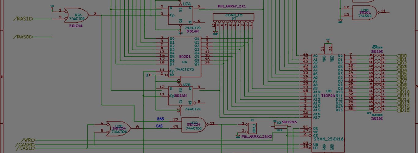
We all need some small success stories from time to time, so here are a few shots:
https://milliways.chance.ru/~tnt23/pics/amiga/boot1.jpg
https://milliways.chance.ru/~tnt23/pics/amiga/boot2.jpg
https://milliways.chance.ru/~tnt23/pics/amiga/boot3.jpg
https://milliways.chance.ru/~tnt23/pics/amiga/boot4.jpg
https://milliways.chance.ru/~tnt23/pics/amiga/boot5.jpg
https://milliways.chance.ru/~tnt23/pics/amiga/boot6.jpg
I took the Fredo’s Boot Intro archive and used one of its intros (small pieces of executable code, placed in boot block area, much like virus) to boot from my MCU pretending it is an external floppy. And it worked!
There is still a lot of work to do, and a lot of walls to bang my head against, like attaching DRAM big enough to store almost 2.5megs of floppy image, or interfacing with CompactFlash/SecureDigital memory cards and writing some ugly LCD/buttons interface.
Hey sorry I just approved this — didn’t see this until just now.
Hell yeah I need some success stories because there sure isn’t anything successful going on here.
Wow. That is very cool. Good work. Glad to hear someone is succeeding!
That’s great.
I’m still spinning my wheels here, and not getting anywhere quickly. I just keep going around and around. It’s frustrating.
Success wouldn’t be that exciting without failures and a lot of dull work.
Keep it up with your research, I am sure there will be your victory day soon.
I suppose you are right. Thanks for the words of encouragement.