I think this is timing from like 97 or so, and this is pretty good. I’ve switched to 93 for the time being, because I’ve had the best results with that. This still shows accurate reading of this particular set of signals.
I think this is timing from like 97 or so, and this is pretty good. I’ve switched to 93 for the time being, because I’ve had the best results with that. This still shows accurate reading of this particular set of signals.
![]()
techtravels.org is a blog that features home-grown open-source hardware and software projects.
Copyright © 2025 techtravels.org Powered by WordPress
How do you generate the lower pulse chain, and in which code section?
Haven’t seen your up-to-date code – do you ‘re-sync’ on every high to low transition?
When I enter a section of importance, I raise a pin, and when I exit that section of code I lower it. Processing of both the edge and timeout occur in the same ISR, but I do a couple IFs to determine the flow BEFORE actualling setting/clearing a pin.
I do that for processing an edge, processing a HIGH (ie timeout condition), and when I notify the PC a byte is ready.
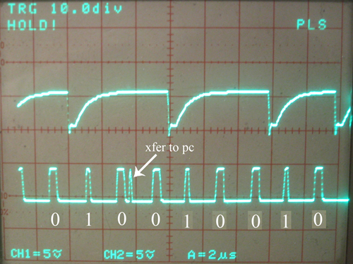
What’s nice is that the routines are all different lengths, so even though I use the same pin, I can tell exactly which routine it is based on the pulse width. The smallest is the xfer, next biggest the edge, and the largest is a high.
These things never happen at the same time(although they can be pretty close in time) — and they always finish before another one could begin, so its safe using one pin.
Yeah I resync on every high to low. Actually, to keep it simple, I resync on EVERY trigger of the ISR, which could be edge or timeout. I reset the RTCC to 0 for the first instruction in the ISR.
For an edge, this means the 2us(or 1.95 or whatever) timeout begins at the time the edge is detected(which takes horribly long, like 100-200ns) and so that means the next timeout should be right at the beginning of the second bitcell. If its 150ns into the first cell, and I’m using 2us timeout, the next timeout should occur at 2.15us.
For a timeout, clearing RTCC at the beginning of the ISR has a very minor effect. The timeout occurs when the RTCC rolls from 255 to 0, and so clearing it at the start of the ISR really takes the RTCC from a very small value (it’s actually 3 cycles, 60ns, which is how long it takes the ISR to get called) back to 0.
Its this setting RTCC=0 that provides the sync.
Oh, and I have plenty of speed/cycles/time to do the pin setting and clearing. I manually counted each of my routines and have plenty of time. As you can see from the image, there’s still a fair bit (relatively speaking) of time in between the processing……
Clever explanations, thanks. I guess I understand now the whole thing much better.
Just one thing about the edge (we’re talking negative front edge, from high to low, aren’t we?): according to your scope scale, the ‘edge’ spike occurs good 0.5us later.
That’s 25% of the bit cell. Quite a bit of a delay, isn’t it? Although it seems to work for almost all your data.
Another question, would you like to try again that concept with starting timer at an edge, then on the next edge measuring the time between the two and shift 10, 100 or 1000 into output based on what margins that time falls into?
(The only quirk I can see here is when you already have 6 or 7 bits of data waiting for another bit or two to transfer the whole byte to PC, and two or three more arrive.)
Yes, we’re talking about the negative-going falling front edge.
Right — I think *most* of the delay comes from the fact that SX/B has to preserve some variables coming INTO the ISR, and this adds 14 cycles of delay. I also have about 11 cycles of additional code BEFORE the debug pin goes high. Oh, and the SX takes 6 cycles (maximum) before calling the ISR on edge. SO this is 31 cycles or potentially .62us. I never broke this down like this before.
See because I don’t know whether the ISR triggered via an edge or a timeout yet, I can’t raise the pin immediately upon entry. Obviously it takes code(and cycles) to determine this…….
And remember, the edge is actually DETECTED much earlier than the debug pin shows….. so there isn’t really a lag time in detection, just a lag time in reaction to the fact that it occurred.
This actually works well, and I haven’t seen any ill effects as a result of it.
Well I *have* been working on that new model here and there. Actually I worked on it last night — the problem is I haven’t gotten ANY good data yet. I solve (or more accurately, Guenther solves: I wrote my code based on Guenthers) this problem by having two 8-bit variables and doing a
rl SRL (low)
rl SRH (high)
where the carry bit connects the two bytes. Then I xfer SRH to the PC when I get to 8 bits.
I also don’t care for the fact that we bombard the shift register with a bunch of data all at once. It can be up to 4 bits…… It seems counter-intuitive because the data comes in slowly & regularly every 2us — so why wait until the next edge to store it…. But, of course, this is necessary, I think, in this model.
Hey how often do you think I need to call the ISR in this model? Every 1/2 microsecond? My fear is that since most of the code happens in MAIN, that we aren’t providing enough time to main to process — it really gets interupted very often…..The ISR is REALLY SHORT though. Like 3 instructions total for the whole ISR or something. All I do is increment the ISRcounter
In your movie, there are frames showing long idle periods and a lot of xfer spikes (well, they really look like xfer spikes, not like high detected spikes) during these – do they lead to filling your data with zeroes?
Will you post your updated code?
Actually they aren’t xfer spikes. They are simply RTCC rollover spikes. Because the drive is idle, the ISR is very short, so I guess they look like xfer spikes. When the SX is idling, it doesn’t add anything to shift register, hence doesn’t transfer anything to the PC, hence the pulse width of the debug pin is small.
I’ll post my updated code, but I’m afraid its almost always in a constant state of flux — but the basics of how the code works is the same.
I was working on the “new model” last night, and did find a couple minor problems. The SX is still detecting multiple edges because the loop to do is very tight. This can easily be handled, but I don’t like the fact that the ISR is real short, and main is real long.