I took David’s advice, and I rewrote the code last night. Some highlights:
1. ISR is entirely in assembly. Although I haven’t manually counted, it appears to be about 400ns in length.
2. ISR triggers only due to an edge now. I admit I do like the fact that there are no longer RTCC-triggered interrupts. The RTCC runs freely now and is not reset or resync’d. The difference in time(ticks) between the edges define the data.
3. I’m using a prescaler of 1:2 on the RTCC, so the RTCC rollsover every 10.24us. This means that each RTCC tick happens every (10240ns / 256=) 40ns.
4. Edge detection seems to be working perfect.
5. Main is completely empty. Just a loop to keep it alive
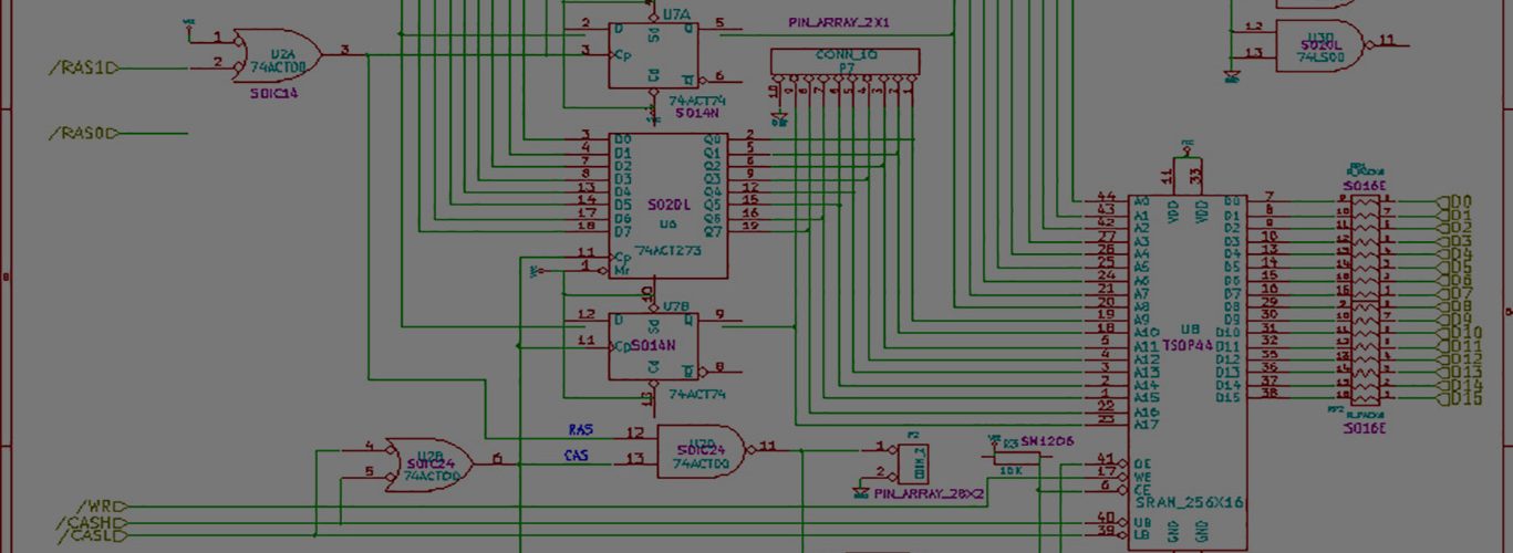
I don’t like the fact that the shift register gets slammed with up to 4 bits all at once. I’m using a
CLC
RL SRL
RL SRH
and once I have shifted 8 times, I transfer SRH to the PC.
A transfer can happen at inter-bit times, but thats ok — the ISR can run forever, up to 4us from the start.
I’ll post results if I can get some! 🙂
Well. It’s just more of the same.
I’m getting some sector headers decoded ok. No data checksums are passing.
I’d like to transfer the time between edges to the PC, but it’s just too fast. I tried it. Since there are so many 4us cells, the PC just isn’t fast enough.
I’m getting both types of errors. Not enough time between edges for a valid signal, and too much time between edges for a valid signal.
I bumped my prescaler all the way out to 1:8 so I could see exactly how long some of them were. I saw one out at 22.8us between edges.
If all the different methods yield similar results, then there must be something fundamentally wrong with my approach.
I need a scope, perhaps a PC attached one, that can record about 1 second worth of data at 500kbps. I need to look at a complete sample and find the problem areas. Anyone know of one, cheap?
I’ve also contemplated going USB just so I can get some decent speed to the PC. This speed limitation is irritating at best. This sort of breaks the basic idea of my project, but at this point I’m frustrated beyond belief.
It is probably worth mentioning that whatever data comes from the drive when seeking (stepping) and a while after, should be treated as garbage.
Do you take RDY signal in account? It should tell when the motor has been spinned up and the data flow can be trusted.
HI. Thanks. Yeah as the motor spins up, even for an individual track read, you get usually one byte of garbage right at the beginning, and then IIRC about 13K bytes of zeros. This translates to roughly 208 milliseconds of delay. With the way I handle the data, garbage at the beginning is OK anyways. I basically search for the very first sector header, and since reads always (well, almost always) starts in the middle of the data portion of the sector, any initial data whether it be good data from the middle of a sector or startup data from the spin-up is treated the same. ie not used.
My earlier code (two sources of interrupt) used the idle-handling code to virtually eliminate this. Since there are no edges happening during all the zeros, the code handles it as if the drive was seeking to the next sector, for instance.
David’s idea, the latest version of my code, is “edge-activated”, and it measures the distance(time) between edges. Once again, since there are no edges, the very next edge of valid data will result in the time being huge — or at least just plain incorrect. So a “long” run of no activity is easy to deal with.
My next plan is to embed the actual errors into the real data as illegal patterns, so at least I know WHERE and WHEN the errors occurred. Pick two patterns, one that means time between edges was too small, and one that means it was too large. This way I’ll be able to see if the problem happens consistently in one area, or follows or trails common bytes.
I was also thinking about having the SX do the work of making sure the data is byte-aligned before sending it to the PC. It would do this by detecting a bit-shifted SYNC, and fixing both the sync and the following data. I have plenty of time between edges, minimum 4us, and my routine is currently tiny. This gives me +/- 3us of extra processing time. This shouldn’t be too hard. I’d just have to start storing an extra byte or two. Then I’d need to check those bytes against an array, which would be indexed by the number of bits it needs shifted by.
BTW, how much internal memory does your SX have? some 16K should be enough to store incoming bytes size of a track.
16K? 🙂 Are you kidding? 🙂
I have 136 bytes of RAM.
Obviously I would jam the whole track in memory and then xfer it afterwards if I had the choice.
I was just asking after all! =)