

 keith
keith
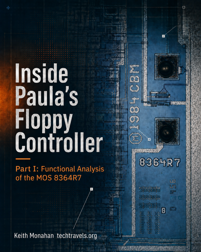
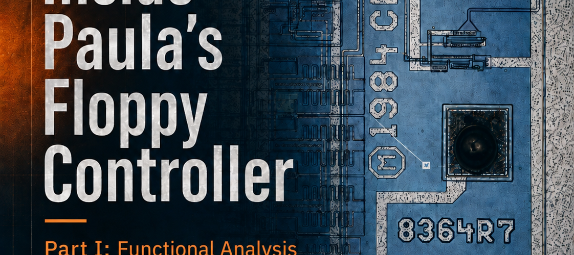
Cover art and die photograph by Keith Monahan
I have been working with Amiga floppy disks from the outside since 2005, starting with the Amiga Floppy Project and the hardware that followed it. What I never had was a clear picture of what Paula was actually doing inside the machine.
In July 2023, Frank Wolf and ttlworks published a transistor-level dissection of the 8364R7 Paula: die photographs, vectorized layouts, and a traced schematic of the whole chip. Section 10, the floppy controller, was left uninterpreted.
This paper interprets it.
What I did
I worked through all twenty-two modules of section 10, 10a through 10v, traced the connectivity, and reduced it to logic and state behavior. I then simulated the extracted logic and checked the result against the Amiga Hardware Reference Manual and Glenn Keller’s data separator patent, US 4,780,844.
What is in it
52 pages, seven chapters, four appendices:
- What a floppy disk controller has to do, and the three ways of splitting that work between the chip, the drive, and software.
- Where Paula sits in the Amiga floppy subsystem, alongside the CIAs, Agnus, and the driver software.
- The complete read path: input conditioning, edge detection, clock and data separation, deserialization, sync detection, byte and word framing, the three-word buffer, and DMA into chip RAM.
- The complete write path: DMA out of chip RAM, serialization, write timing, write precompensation, and the write data and write gate outputs.
- Three Paula mysteries explained from the circuit: why
DSKLENhas to be written twice, why the last three write bits are lost, and why the final read word sometimes does not arrive. - Appendices: a module map, a register, pin and signal reference, a glossary, and a summary of the main conclusions.
Part I covers the functional level: what each block does and how the blocks work together. Part II will cover the circuits themselves, with transistor paths, PLA reductions, and timing.
The paper
Inside Paula’s Floppy Controller, Part I: Functional Analysis of the MOS 8364R7 (PDF, 52 pages, revised September 2026)
Revised edition, September 2026
The PDF linked above is a revised edition. The first edition was published August 6, 2026. What changed:
- The three questions the first edition marked “not extractable from the drawn schematic” are now answered: the data separator’s pacing arithmetic, the transfer terminal count, and the recovered-clock formation. Chapters 4, 6, and 7 carry the results.
- Two new evidence sources made that possible: full-band silicon images that ttlworks published in response to the first edition, and my own photography of a Paula die.
- The final-read-word mystery in Chapter 6 now has a complete mechanism, combining the recovered terminal-count circuit with hardware measurements published by Toni Wilen.
- The disk DMA request timing has been corroborated with logic-analyzer measurements on real Amiga hardware.
- The first edition’s confidence vocabulary and status graphics are gone. Uncertainty is stated in plain language where it remains, and Chapter 7 collects what is still open.
Comments and corrections: insidepaula@techtravels.org


Add comment