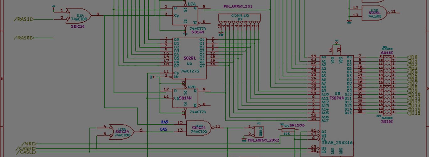
Well I’m now inline with a data tap, so I have access to all 25 pins on the floppy interface between the amiga and the floppy drive. I used to attach to the DB23 on the pass-thru port of the floppy drive, but I wanted to get in the middle.
Looking at the various pins with my scope, though, I can’t seem to locate the step pin properly. It’s supposed to be pin 18 on the DB23, or pin 19 on a DB25(since we skip pin 13) — but scoping that pin shows absolutely NOTHING happening.
Tim: if you are watching, how wide was the step pulse you were seeing coming from the amiga? And are there any serious discrepencies regarding the published pinouts? I have several sources, and they all line up.
On at least one of the pins, I see this pulse that seems to change pulse width. I either get a 8ms pulse or a 27+ms pulse. Measured something like 234ms apart.
I’m going to keep playing around…..
Basically what I’m doing is starting a disk to disk copy on the amiga, which loads the first half of the disk into memory. This causes the drive to step from cyl 0 to cyl 79 on just one side of the disk. So I should be expecting PIN 18 to step with each successive track that gets copied to memory, and I’m not.
No movement at all on the step pin.
When transferring, I get activity on the following pins on the DB23:
Pins 1, 2, and 8 which are Disk Ready, Read Data, and Motor Control.
Pins 13, 14, 19, 21, and 22 which are Side select, Write protect, Dir(head direction), Sel1, and Index.
All the pins make sense(I think) except nothing on 18…
It’s ALWAYS the cables. I should know better.
It turns out the pinning to go from the DB25M amiga side of the cable to the DB23M on the drive side of a standard Commodore Amiga Floppy drive cable has a semi-odd setup.
Commodore Amiga Floppy Drive pinouts DB25M to DB23M
DB25M —– DB23M
1—————–1
2—————–2
3—————–3
4—————–4
5—————–5
6—————–6
7—————–7
8—————–8
9—————–9
10—————10
11—————11
12—————12
13—————N/C
14—————13
15—————14
16—————15
17—————16
18—————17
19—————18
20—————19
21—————20
22—————21
23—————22
24—————23
25————–N/C
This chart is now right. I screwed up. Pins 13 and 25 get chopped off the right hand side of the DB25, so the TOP of the DB25 is
TOP: 1 2 3 4 5 6 7 8 9 10 11 12 (which is 1-12 on the DB23)
BOTTOM: 14 15 16 17 18 19 20 21 22 23 24 (which is 13-23 on the DB23)
Hmmm, I made my DB23 out of DB25 by hacking off pins 14 and 25, and got pin numbering like this:
TOP ROW: 1 2 3 4 5 6 7 8 9 10 11 12 13
BOTTOM: 14 15 16 17 18 19 20 21 22 23
and everything was in accordance with schematics from my A500 guide.
STEP pulse itself is rather narrow, can be 0.5us or such.
Now that I fixed my cable diagram above, my self-fulfilling prophecy is screwed up 🙂
I can’t pick up a STEP pulse to save my ass on my scope on DB25 pin 19, ie DB23 pin 18. Pulling my hair out.
So did you get the wrong pin? I don’t happen to have schematics with me, only an internal floppy bus pinout, where STEP is on pin 20.
Mind you, catching one single STEP pulse can be tricky. I used DiskMonTools to read tracks 0 and 79 to get a bunch of STEP pulses to be scoped nicely.
I really don’t know what’s going on.
I have reliable sources for the pinout information, and they all line up, so the DB23 on the back of the amiga, pin 18 should be STEP. Commodore’s cable that goes from DB23 on the amiga to DB25 on the back of the drive move pin 18 to pin 19 on the DB25. Putting a scope on pin 19 yields absolutely nothing.
I have been copying a file from the disk to ram: and so there are many step pulses happening, but I simply don’t see them on the pin. No clue why.
I should be able to see them on a storage scope, right?
can you not connect scope to pin 20 on floppy (like Tim) to prove you get step pulses first
If you get the pulses then you know it’s in the cable and any transformations / crossover ?
Then just use multimeter to check where the pin 20 end of cable (at floppy end) goes to on the db23 ?
Well, pin 20 is off the internal floppy header, and I’m working off the external drive connector, where step is pin 18 on the DB23. Now since its a bus, the signals should be present at both places. But I’m sure the step pulses are getting to the drive, because the drive is stepping, I’m sure of that.
I’ve already pinned-out all cables involved, the pinouts you see in the second comment is exactly a multimeter check of the cable.
I have a “data tap” in between the DB25 on the floppy end of the cable, and the floppy drive. This is where I’m getting access to the pins. The DB23 connects directly to the amiga via a DB23.
I finally caught one of these elusive beasts — the step pulse.
On the same pin as I’ve been looking.
Tim: thanks for the tip about using diskmon to go from track 0 to track 79. I needed alot of pulses in a reasonable amount of time — so I could press “hold” on the scope.
The pulses from the amiga appear to be about 1.45us(slow rise time, out to 2.21us to return to full 5v) wide. They were fairly irregular and my scope really didn’t want to trip.