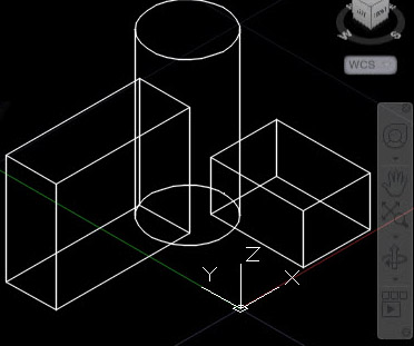
So I’d really like to be able to rotate 3D objects using this computer. There’s some problems though that make it a little harder than normal.
- The 68000 doesn’t have any integrated Floating Point Unit(FPU) integrated. What this means is that it “speaks” just integers, and there are no associated instructions for natively multiplying floats, for instance. There also isn’t one on my board.
- 3D coordinates use floating point numbers extensively. Many associated 3D functions need to operate on those numbers.
- I have no C toolchain. No C toolchain means that SOFTWARE support for floating point really doesn’t exist either. There aren’t exactly 68000 ready to go FP routines, but they could likely be ported from other OS’s like Mac or Amiga.
I’ve got a few ideas on how to solve this one:
- I think I’m going to use fixed point numbers. This definitely simplifies things.
- I’ll use one 16-bit integer to store the first part to the left of the decimal point, which I’m sure has a fancy name I don’t know. I looked at some .OBJ files and usually that portion of the x,y,z coordinate seems to be low numbers……like 0, 1, 2, or 45. I’ll have 65536 which is plenty.
- I’ll also use one 16-bit integer to store the part the right of the decimal point, the fractional part. This gives me 1/65536 = .000015259 granularity. Sounds good at first glance? Let’s walk before we run.
- I’ll need a set of basic math functions like multiplication and addition for these numbers.
- In order to do 3d transformations and 3d->2d projection, you need to do matrix math, including matrix multiplication. I plan using orthogonal projection, which I think is the easiest.
- I need to understand if the 68000 is going to be too slow at some parts of this, and whether I need to create custom Verilog hardware to speed it up.
Do you have any experience on using fixed point math to do 3d graphics on non-FPU computers? Does my approach sound reasonable?
Let me know in the comments!

Fixed point 3D graphics is perfectly doable. The original Playstation 1 used fixed point: https://www.quora.com/Why-didnt-the-original-Playstation-support-floating-point
I would suggest using perspective projection. It’s no more difficult than orthographic projection, it just uses a different transformation matrix. The result will look more natural. Orthographic projection looks like an architect’s or draftsman’s diagram, with a slightly odd appearance.
What’s your plan for line rendering? Once you’ve transformed and projected the vertices into screen coordinates, you need some way to draw a line between them. For the type of simple 3D scene in your example photo, you might benefit more from hardware accelerated line drawing than hardware accelerated 3D transforms.
Thanks much for taking the time to reply!
Will check out perspective projection. My second glance at perspective sure looks like there’s a ton more input variables to the equations, requires division, many more sin/cos lookups, and so on. I’ll try and wrap my head around this.
For some reason, I thought I’d be rendering a line between the 3D vertices first in 3D space, and then projecting all of the points to 2D. I suppose doing the line drawing in 2D is simpler.
The 2D line drawing algorithm I’ve been using is a modified version from here:
https://lineout.atari.org/downloads/LINEALG.TXT
(ignore the original coders comments, it sounds like he’s twelve, but the assembly does seem to work!)
So if I go from a .OBJ file, and I load all of the vertices into some type of “array”, then project them into a matching 2D array and maintain some index value between them, and then use the face lines and indexes to determine the various endpoints for the 2D line drawing algorithm, does this sound right? Obviously if I’m transforming the 3D points, I’ll need to do that prior to the projection.
Just considering this now, that I really don’t have a form of DMA. Either the video driver, which is verilog, and read-only operations copies frame buffer to screen, or the CPU (full r/w operations) are the two accessors of the SRAM. I suppose I could do some sort of memory mapped peripheral, whereby you’d pass in(via writing to a particular set of addresses) x1/y1, x2/y2, and then some point later, the hardware returns an array of coordinates that make up that line, pulsed out at one per memory read or something. Sounds a little complicated at first glance. Right now, most of my hardware peripherals return just a single data value on the databus.
Thanks again!
Yes, your general plan of attack for .OBJ files sounds good. And if you’ve already got a working 2D line drawing solution, great.
I used to do 3D graphics programming for video game companies. It’s been a long time now, but I don’t think there’s a big difference in the amount of math required at run-time for perspective vs orthographic projection. It’s true there’s a perspective projection matrix that must be computed, but that can be precomputed ahead of time (when you write your code) and the results stored. The calculation’s inputs are the field-of-view angle of your virtual camera, and the distances to the near and far clipping planes. No division required at run-time – you just multiply your view-space vector by the precomputed perspective projection matrix to get the screen-space coordinate.
Some years ago, I wrote a series of blog posts about a planned project called “3D Graphics Thingy”, which was to be an attempt at simple 3D graphics using hardware similar to yours. I never built it, but you might find the analysis interesting. https://www.bigmessowires.com/category/3dgt/
Good luck!
You definitely have to do a division for each point you do perspective on, but for a line you only have to transform (multiply the matrix) on the endpoints, and then draw the line in 2d.
Going with fixed point is certainly the way to go on the amiga. The rouble with fixed point is that it is fixed and thus if you have files with big integer parts 28:4 might be a better fit, but if you have files with coords mostly in the fractional end 8:24 might be a better fit. There is simply no way for you tomake a choice that fits every case. You could start by scanning the .obj a try to map all the coords to whatever fixedpoint format you have decided. Personally I have integer coords and 24:8 fixed point in my transform matrix but then again in my code I have absolute control over the coords to begin with – as i said you would probably have to scan and convert your .obj when loading