While there are some other bug fixes and documentation to be done on what’s already been implemented, I started thinking about writing ADF’s to disk over the last few days.
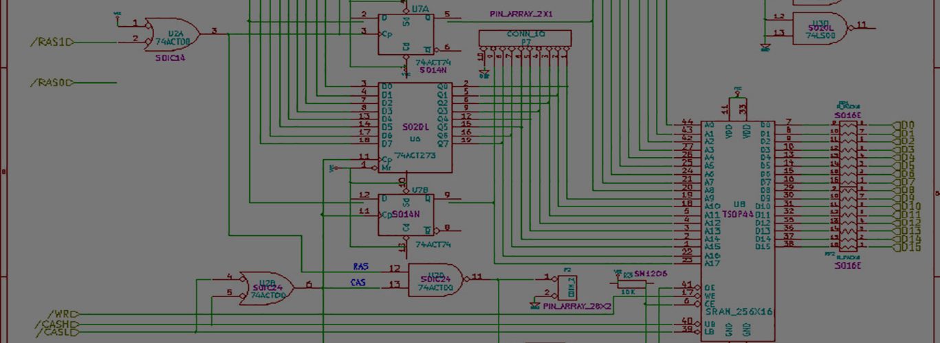
While the hardware part of it is already in place, there are some things that would need done:
- The interrupt service routine would need modified to not just read data by reacting to edges, but now extract a bit from memory and put an appropriate pulse on the writedata pin. Floppy drive specs say the pulse should be 0.1us to 1.1us wide.
- Write an SX routine that would receive data from the PC and store it in the fram. This would need to checksum the received data and either error out or request a retransmit.
- Write PC routines that would create the full MFM track: I’d need to create a header (easy enough, use sector numbers, 11-sector number, track number, and then checksum everything), then MFM encode the data. I’m already doing much of this in the decode portion, so I can basically do the opposite for encoding.
- Of course there’ll need to be a “controlling” pc routine, much like my current readtrack() routine.
So the whole process of writing a disk would go something like this:
- Have user browse for the filename, select the file, load it into a “floppydisk” structure/object that currently exists.
- Rewind and make sure I’m at track 0.
- Create the first track’s data.
- Send a command to the SX to tell it to receive a track’s worth of data.
- Send the data making sure it’s been received correctly.
- Tell the SX to write the track.
- SX enables the write gate by lowering it, and starts pulsing out data, pausing the appropriate times for 0-bits.
I don’t see any major hangups, although there are a few timing related things to get right. I’ve got make sure 18ms has passed after each step pulse. And I’ve got to make sure 100us has passed since I’ve selected the drive(this is mainly during setup for the first trak). For the last track, I need to make sure I pause for 650us after the last track is written. I also have to make sure that the time from the write gate dropping to the first bit MUST be 8us or less. Same with the final bit, I have to raise that write-gate within 8us after the last pulse.
I’ve got to look into creating a gap, sending SYNC words, learning wtf pre-write compensation is, etc.
My compliments for your efforts in bringing an alternative to transfer data to/from the old Amiga computers.
Recently a friend of mine donated me his old machine , a working Amiga 500, wich came only with the PSU, ence i have no access to software nor the means of supplying disks to it.
My collection of amiga software was lost in the course of time, so i´m looking at your project as a solution to revive this old machine, i need at least a workbench disk in usable condition to start reliving the old glory days.
This may sound noob to you, but my skills at electronics are somewhat a compromiz ,and i would like to avoid if possible smd components.I noticed that parallax supply also microcontrollers in dp packages, do you see any problem building a cirquit like yours, with the SX28AC/DP-G as the Micro ? also, are there any other alternatives to the smd fram.. in dp package ?
Thanks in advance
Raimundo
Hi Raimundo,
Welcome. Thanks for the comment.
No, there is absolutely no problem with using the SX28AC/DP-G. As a matter of fact, the previous version of my project used exactly that one.
Look here
https://techtravels.org/?p=138
and you can see an old picture of my project using the dip version.
Note that the protoboards with the surface mount SX28 are like $10.00 which is really cheap and available…..
You’ll have a harder time with the ramtron fram in dip version. Trust me, I WANTED dip fram to begin with, but they didn’t have it. If its any consolation, I never did SMT stuff before this project. The fram is actually pretty wide spacing for SMT, I forget the details — but it was actually pretty easy to solder onto a DIP adapter board for the first one, and easy to solder onto the $10.00 protoboard.
you might want to read here
https://techtravels.org/?p=65#comments
and here
https://techtravels.org/?p=67
Unless Ramtron happens to now have a DIP version, you can’t simply just replace with another type of memory because Ramtron has custom op-codes for communicating with it. Unless this is some standard that I haven’t found out, you’d have to rewrite a considerable portion of the routines to make them compatible.
At the minimum, make sure the memory is SERIAL, and that it can take a fairly high clock rate of 5mbps or better. Oh, and has minimum 16k BYTES (remember most memory sizes are quoted in K bits)
Oh hey, last but not least, the parallax $10.00 protoboard has a matching SOIC-8 pad that fits the memory perfectly….. Its definitely a match made in heaven AND was well worth the minor trouble.
If you have 1/2 decent solder skills, you should be ok with what needs to be done.
Feel free to follow up with questions comments etc
thanks again