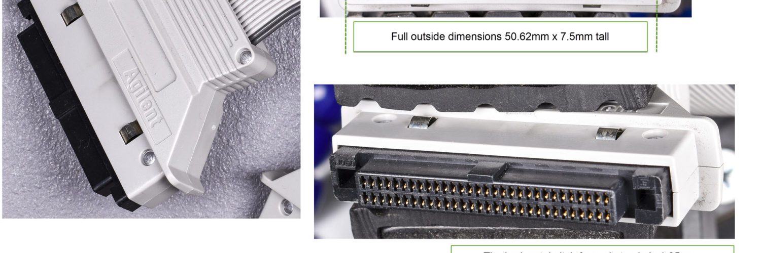
So for today ladies and gentlemen, I present a teardown of an HP/Agilent logic analyzer cable. I think this is part number 16715-61601. This cable is used to connect one of a series of 40-pin compatible modules (many of the 167xx series, but not all) from the 60-pin connector on the LA side, to the 40-pin connectors that supports a variety pod adapters. The most popular, at least in my world, of the 40-pin pod adapters is the flying lead one, the venerable Agilent 01650-61608 pod adapters.
While I’m still trying to identify some of the connector part numbers used in this cable, the 60-pin adapter may be the Hirose HIF6 series.
I have some initial connector images and guesses, and I was slightly off in pitch measurements.
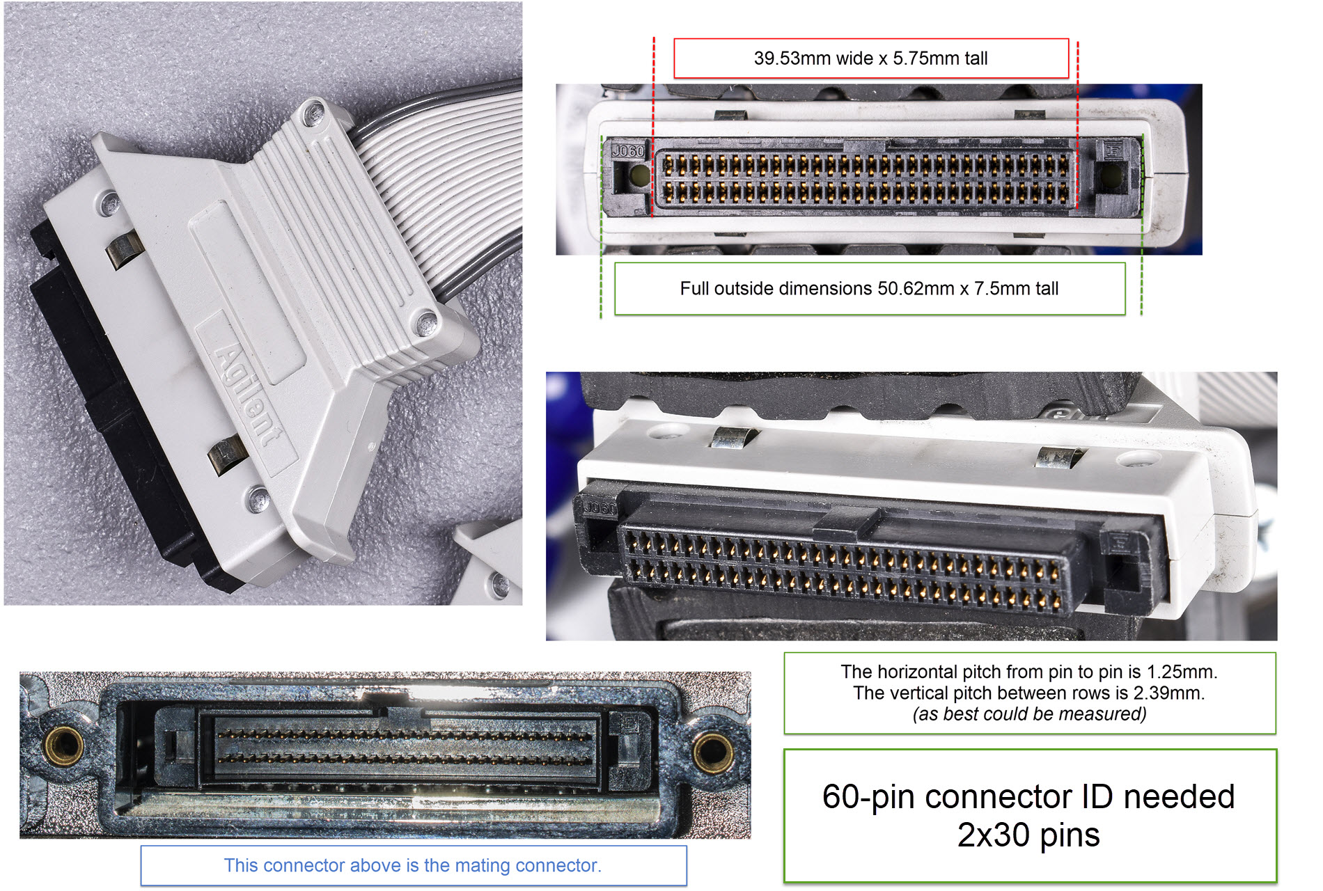
The pitch is actually 1.27mm, and 2.5mm between rows. Information on the connector and pitch has come from always helpful redditors in this post, including 1Davide!
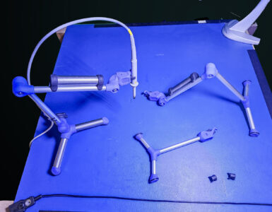
The aluminum rivets used to hold this connector together bothered the heck out of me, because I couldn’t simply remove a couple screws. This sent me on a mission to buy a small dremel-compatible drill press accessory from Home Depot which I used my older Sears Craftsman dremel tool with, to drill out the 1.71mm diameter rivets (with a 2.75mm head) using a 3/64″ drill bit. Worked fantastic, and please enjoy the fruits of my labor in the gallery below.
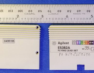
The connector hoods show part number 16715-45202 for the 60-pin side, and 16715-45201 for the 40-pin side.
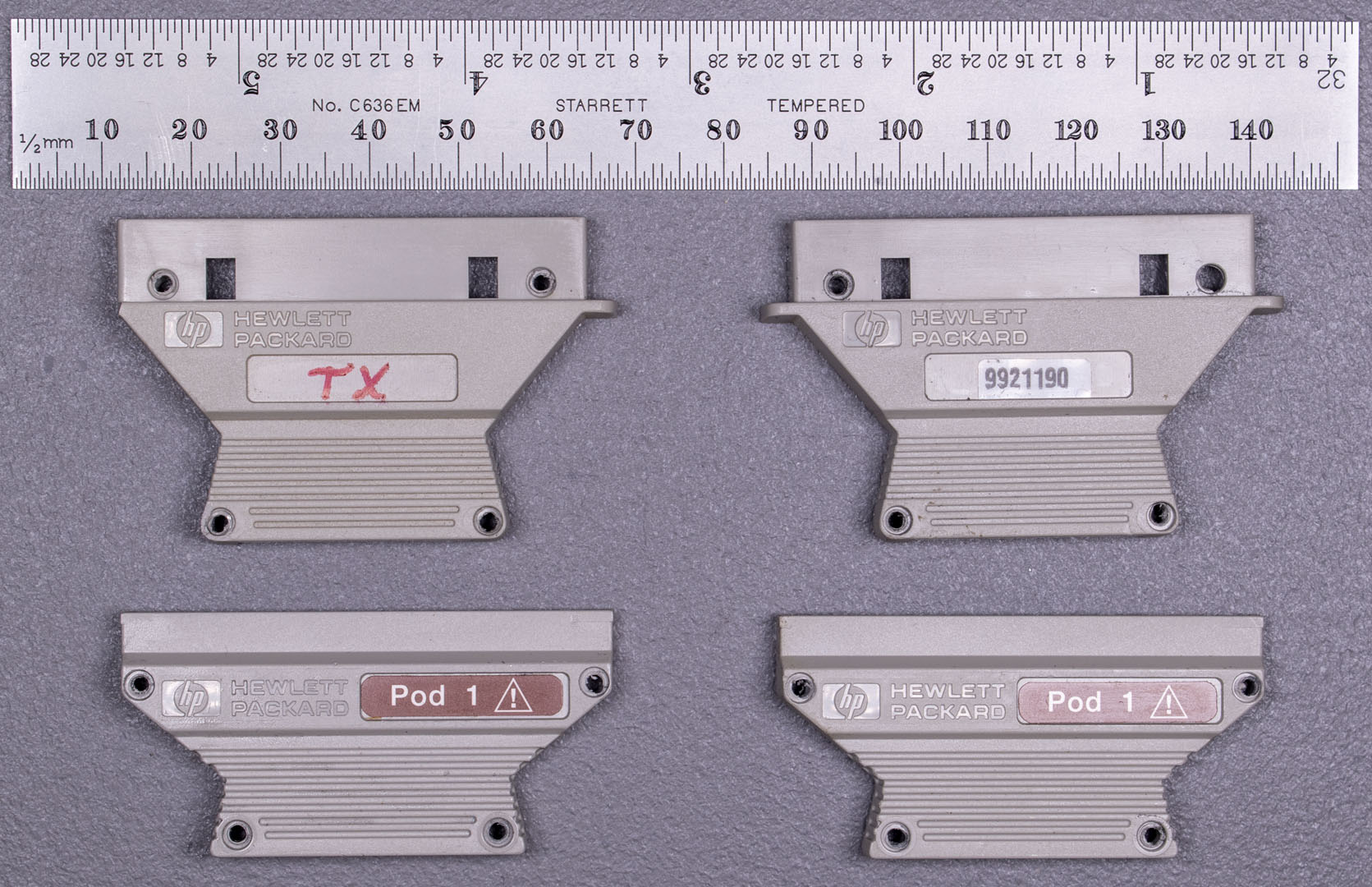


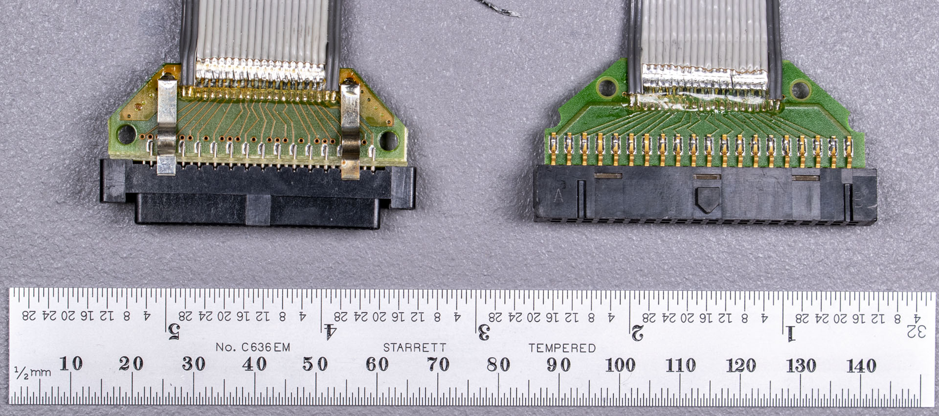

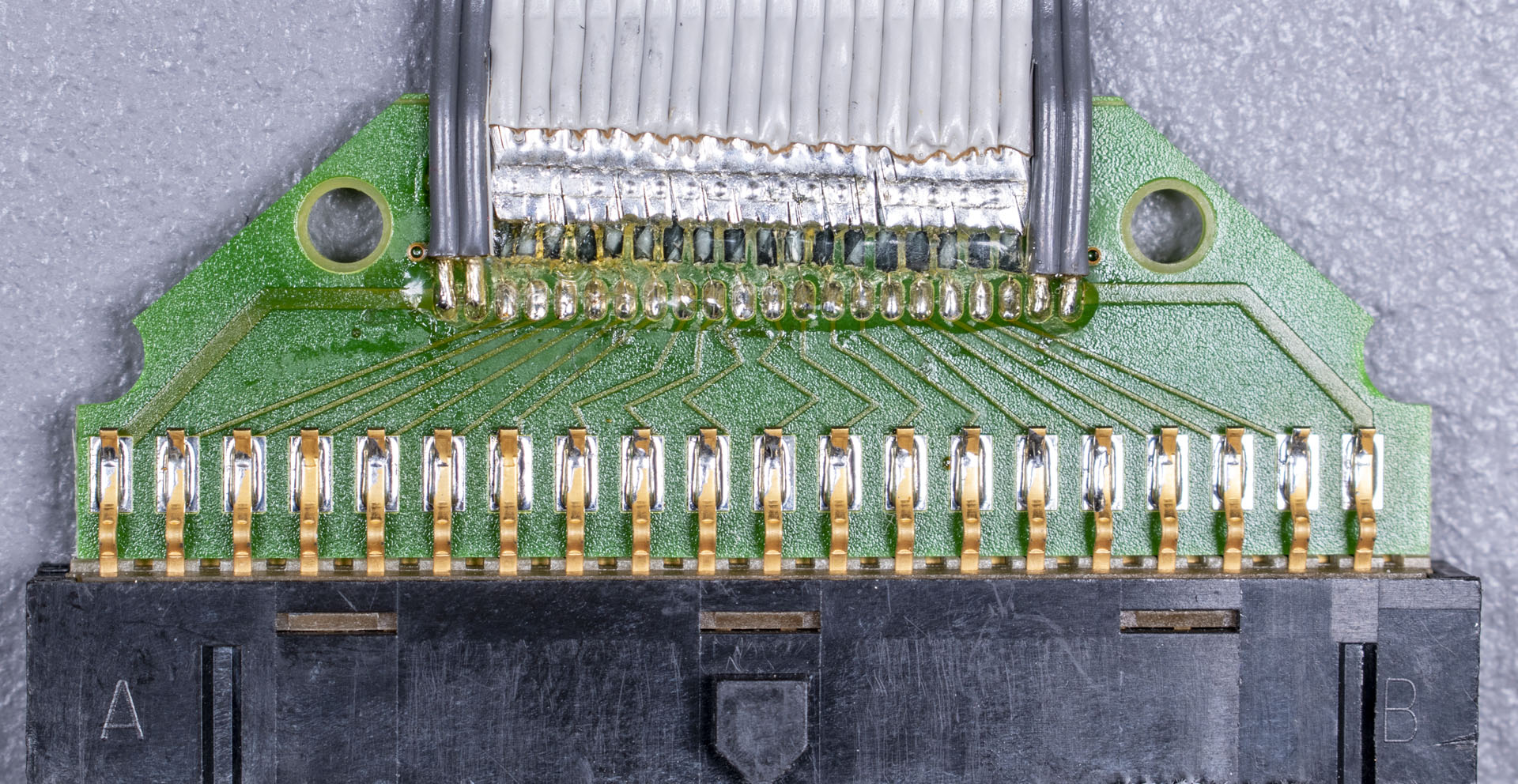

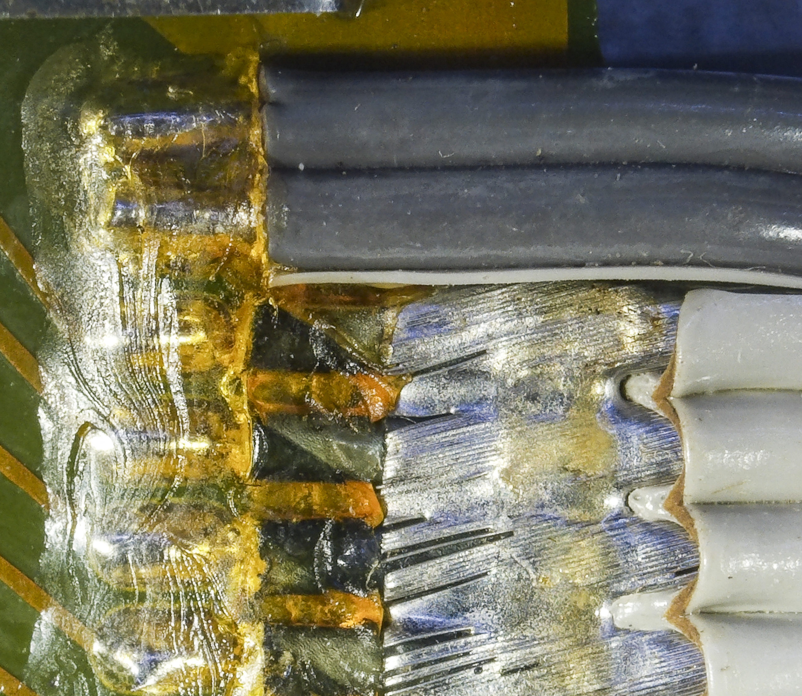
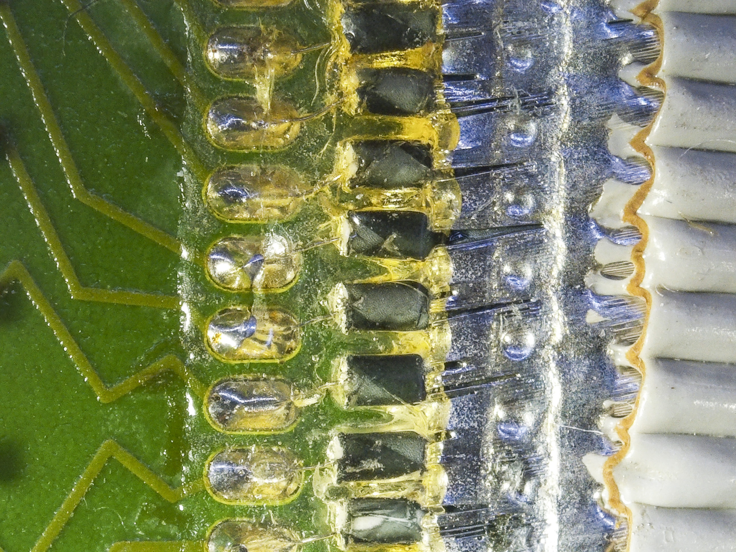

The cable assembly is made up of the 60-pin connector side which then branches into two 24.5mm wide cables, one going to Pod 1 (40-pin), and one going to Pod 2(40-pin). Each of these cables, at first glance appears to be a normal flat ribbon cable, but actually has a unique construction. The center 18 wires are lossy ribbon mini-coax cables with an outside stranded shield, which is soldered together, and a center conductor that carries the signal. The end wires appear to me as solid conductors used for power and ground.
It’s not just small gauge coax, but small gauge lossy coax, so the center conductor is resistance wire with a resistance in the order of 10-100 ohm/meter. This resistance dampens any ringing that might occur in these cables. Both the source (the passive pods) and logic analyzer inputs are much higher impedance than the cable, unlike most RF circuits, so there will be impedance mismatches. The lossy nature helps mitigate this. See page 14-17 of the Tektronix Oscilloscope Probe Circuit Concepts book. It talks about scope probes, but those are not all that different except that logic analyzers are lower impedance (10k LA and 100k probe instead of 1M scope and 10M probe).
alm from eevblog
You can see that the center signal conductor has a black with gray-stripe jacket which keeps it isolated from the stranded shielding of the mini coax. For reference purposes, those mini-coaxes measure about 20.5mm across for all 18 of them. This puts them at ~1.14mm OD for each.
What I didn’t closely photograph is the back of the 60-pin connector. That connector has (4) rows of (15) pins each. There’s a very small pass-through PCB on the rear of the 60-pin connector perpendicular with the face of it. All 60 pins pass through it. Then, you have two other circuit boards that mount parallel with the face, in between the top set of 15 pins, and the bottom set of 15 pins. So the sandwich goes pins, first pcb, pins, a space, a second set of pins, second pcb, and bottom pins. Each small PCB is responsible for each pod. Pod 1 PCB and cable is located on the top side of the 60-pin connector near the polarity “key.” This is labeled “side two” in the images — I called it side two just to differentiate it from the other side.
From my post here you can also see another example of similar construction from Agilent on one of their pods. That internal jacket was clear, which was pretty darn cool, but different from what we see here.
I welcome corrections, additional details, etc.
The connector you’re looking for appears to be a FCN-217J060, from the FCN-210 series. HP seems to have used this connector in several places inside and outside equipment from this era.
They were discontinued without a direct replacement, and similar connectors like the HIF6 are dimensionally off enough they likely won’t seat properly.